eMark
100 kW
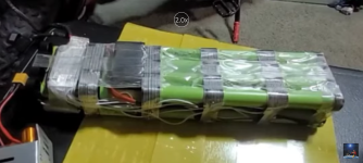
Samsung 25R (2500mAh) is the most popular (20amp rating) name brand reasonably priced 2500mAh cell (green wrap). Your pink wrap cells are no name brand Chinese cells. There are no popular name brand 18650 2500mAh cells that have a pink label wrap. Doubtful the seller will call back. He may not even know the cell manufacturer. Even if he does there is no way knowing if ALL the cells are truly A-grade quality.
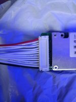
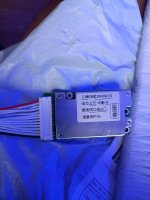
To find out if the problem is cell related or BMS ... you could buy a new replacement BMS. Could be an inexpensive fix before you spend $100-$150 on an AliExpress 13s5p(or 6p) flat scooter battery with no name brand cells (questionable A-grade quality).
If you have the know how you could measure the voltage of each of the 13s 5p groups at the BMS connector. That will tell you if you have weak/dead cell(s) in one (or more) of the thirteen parallel groups (e.g. only 3v or less) that is causing the BMS to shut off the power to the motor. Even if only one of the thirteen 5p parallel groups is under performing the BMS should shut off power to the motor.