
I bought a used juiced 1000 w retroblade motor . Its an entire rim assembly with a drop in bafang 1000w G062 core. Im using the baserunner z10 and cycle analyst. Im getting an error stating that all hall sensors could not be detected. I tested the connections and they were ok. I did see that when I applied 5 volts through the red and black wires that there was no voltage change when rotating the motor and probing the blue, yellow and green hall sensor wires . It seems that Im getting the same reading . I replaced the hall sensors and still the same problem. I tested the continuity of the 5v input and ground of each hall sensor at the pcb and I found that they were connected. Is it possible that this shorted my brand new hall sensors ? I was also getting no voltage change when probing the output pin of each hall sensor with motor rotation. Ive been scouring the message boards and I only found one instance that the pcb board was wanting to be replaced.
You are using an out of date browser. It may not display this or other websites correctly.
You should upgrade or use an alternative browser.
You should upgrade or use an alternative browser.
Replace Bafang hub motor hall board due to short?
- Thread starter vpidlaoan
- Start date
TommyCat
10 kW
Hi vpidlaoan,
And welcome to the forum!")
I would encourage you to look over this motor testing thread to make sure you understand the requirements of bench testing motor hall sensors. I.E. Signal voltage to the sensor…
Testing BLDC motor's Phase Wiring - Hall Sensors and Wiring. - Electricbike.com Ebike Forum
Regards,
T.C.
And welcome to the forum!
I would encourage you to look over this motor testing thread to make sure you understand the requirements of bench testing motor hall sensors. I.E. Signal voltage to the sensor…
Testing BLDC motor's Phase Wiring - Hall Sensors and Wiring. - Electricbike.com Ebike Forum
Regards,
T.C.
I tried the method you had described and despite using the resistor I still get the same voltage output in all the sensors . So I did an experiment. I soldered the 5 v input of the sensor and ground of the sensor to the 5v and ground in the pcb board respectively. The voltage remained the same. It seems like there is a short. Between the 5v and ground of the pcb board. Sure enough I checked the continuity of the 5v and ground and there was no resistance. I suppose my board is toast.
docw009
10 MW
Tommycat wanted you understand how a hall sensor works. The input is the magnet, It has power, ground and an open transistor as the output, Think of the latter as a switch, One end is at ground, and the other is open,
If you put a voltmeter on a bare switch, there's no voltage, right? That was happened in your initial test. In your last experimen. it appears you tied the switch output direct to 5V, That cannot work either, The switch has to short out the power supply and it cannot,
You need something like a 1000 ohm resistor, one end connected to 5V and the other to the Hall sensor output, In the EE world, those are called pullup resistors because they pull the output to +5V until the switch closes, Then it's zero,
Or the easiest thing to do is connect it to the controller, Power it up, Make sure you have +5V across the red/black, Now spin the wheel backwards. The blue, green or yellow output wires will flip between zero andpower if the Halls are working,
Prior to taking my motor apart it appeared that all the hall signals were turned on. I used the baserunner software and the baserunner controller to figure this out. I replaced all the hall sensors using the honeywell ss41 sensors from honeywell and still all the hall signals were turned on.Tommycat wanted you understand how a hall sensor works. The input is the magnet, It has power, ground and an open transistor as the output, Think of the latter as a switch, One end is at ground, and the other is open,
If you put a voltmeter on a bare switch, there's no voltage, right? That was happened in your initial test. In your last experimen. it appears you tied the switch output direct to 5V, That cannot work either, The switch has to short out the power supply and it cannot,
You need something like a 1000 ohm resistor, one end connected to 5V and the other to the Hall sensor output, In the EE world, those are called pullup resistors because they pull the output to +5V until the switch closes, Then it's zero,
Or the easiest thing to do is connect it to the controller, Power it up, Make sure you have +5V across the red/black, Now spin the wheel backwards. The blue, green or yellow output wires will flip between zero andpower if the Halls are working,
I wired the 5v input of the sensor directly to the 5 v input of the pcb board. then I wired the ground of the sensor to the ground of the pcb . The output voltage was still the same. Mind you this is a new sensor so its odd that it would be damaged unless it got damaged by the pcb board. What bothers me is in all of the sensors the 5v pin of the pcb board and the ground are connected based on continuity testing even when the sensor is removed.
I bought a new pcb board since it was nearly the same cost if I try a new set of sensors.
TommyCat
10 kW
From your description you would have 0vdc everywhere, including the 5vdc supply on the board.
If this is accurate, and you don't have burnt or damaged traces on the board. I'd check the solder pads at the hall sensors to make sure two close ones aren't touching. (5vdc and ground legs are right next to each other...)
If those look O.K., remove the connecting wiring harness of the PCB to eliminate that as the source of the short. And check for a final time... (Don't know if you need to reuse the harness...)
Verify that your controller's 5vdc regulated power is still viable.
Last edited:
I replaced the pcb board which includes 3 new hall sensors and still the same problem. My baserunner controller show all the hall sensors to be on at the same time. None were off. When I spin the motor by hand the sensors do not toggle on and off. Although now it seems that the voltage I am getting is less . Im suspecting there may be a short somewhere in the motor cable as it enters the axle into the hub. I work on cars and I know wiring issues are very rare. I am hesitant to pull the cable from the motor . I am not supplying the phasewires with any power, just the 5v and ground to the motor using a battery that supplies 5v (jackery power station usb) . I am using the set up described above and I am using a pull up resistor.
I also covered up the bottom of the new board to make sure it does not make contact with the windings. I believe I soldered good enough that there was no connections between the 6 wires.
I also noted that the board got hot even when only supplying 5 v so I turned off the power.
I also covered up the bottom of the new board to make sure it does not make contact with the windings. I believe I soldered good enough that there was no connections between the 6 wires.
I also noted that the board got hot even when only supplying 5 v so I turned off the power.
Last edited:
TommyCat
10 kW
Please give the actual voltage readings, would be more helpful.My baserunner controller show all the hall sensors to be on at the same time. None were off.
The controller's hall sensor signal wires would have to be connected to the motor in order to provide this information... are they?When I spin the motor by hand the sensors do not toggle on and off.
And if this is a geared hub motor, are you going the correct direction?
Did the new board eliminate the 5vdc short to ground?just the 5v and ground to the motor using a battery that supplies 5v (jackery power station usb)
The resistor method is for bench testing only. I.E. Not connected to the controller. See controller's hall sensor signal connections question above.I am using the set up described above and I am using a pull up resistor.
One resistor is used but swapped between the different sensors as each is tested one at a time with a multi meter.
Check the controller's motor hall sensor output voltages and report what they all are.
I encourage you to carefully re-read that troubleshooting guide.
5vdc external could possibly be used for the supply for the hall sensors, but you would have to tie the grounds together.
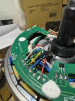
Thanks for all the support. I am using the bench test method. No controller is hooked up. Im supplying 5 volts via a Jackery powerstation using a USB port (5v, 2.4 amps) . As you can see (pic 1) every thing is hooked up as described by TommyCat. Im showing the new PCB board (pic2) and my soldering. Now with the new pcb board the voltage keeps changing between 0.06 to 1.2 v when not moving (pic 3) . I tested one of new hall sensors (pic 4) which I purchased prior to getting a new pcb board and the voltage changes. I hooked it up directly to the 5v source and ground. The voltages were between 0 and 5 v.
When hooked up to my baserunner controller and using the grin software all 3 hall signals were lit up. The grin software has this functionality. When I rotate the wheel I do not see any toggling between on and off. When I tried programming the motor it could not detect a valid hall pattern. This is why I took the motor apart for bench testing. Any input would be greatly appreciated. Im thinking of just using the sensorless mode of the baserunner. Im not sure if this will be as good as the sensored mode.
When hooked up to my baserunner controller and using the grin software all 3 hall signals were lit up. The grin software has this functionality. When I rotate the wheel I do not see any toggling between on and off. When I tried programming the motor it could not detect a valid hall pattern. This is why I took the motor apart for bench testing. Any input would be greatly appreciated. Im thinking of just using the sensorless mode of the baserunner. Im not sure if this will be as good as the sensored mode.
Attachments


Last edited:
Just an update. I did some continuity testing on the wires and it turns out the adapter cable that I bought does not match up with the wiring of the motor. Power and ground were reversed and so were the halls and speed sensor. The blue hall was the green hall, green was blue and the yellow hall was the speed sensor and vice versa. It seems that when Bafang worked with Juiced the wiring set up of the motor is different.
I set up a new testing strategy to eliminate the effect of wiring. I directly wired the 5v and ground to the power source. I also wired the pcb board in accordance to wiring of the Grin baserunner. I am getting voltage changes at each of the hall sensors using the pull up resistor , but the low voltage was 2.65 and the high voltage was 4.98. I had a spare hall sensor so I wired that in place and it was the same result. Im using the honeywell ss41 hall sensors.
There is 5v between the input and ground of each hall sensor but without the resistor , there is no voltage changes noted by my voltmeter. interestingly I see the hall sensors toggle between 4.98 and 0 volts when measuring between the input and output depending on the rotation of the motor.
Is a low voltage of 2.65 and a high of 4.98 enough to trigger the controller?
Attachments


Last edited:
TommyCat
10 kW
Try the test with the correct size resistor as recommended… 1/4 watt, 10K ohm.
It appears you’re using a 22 ohm?
The pictures are a great help. Glad you got the harness sorted, well done!
Most geared hub motors only turn the magnets when going in one direction.
You’re getting closer.
It appears you’re using a 22 ohm?
The pictures are a great help. Glad you got the harness sorted, well done!
Most geared hub motors only turn the magnets when going in one direction.
You’re getting closer.
Update. It turns out the problem was merely that Grin and Bafang (juiced retroblade motor) were using the opposite convention when choosing which connector carries 5v and ground. The reason why the hall sensor voltage was not changing is because 5 v was going into the negative input and so the read out voltage from each sensor was stuck at 5v. Because I could not change the polarity of the controller , I just switched the positive and negative wires within the hub motor and now all hall sensors are now working. I used my old PCB board and soldered the new but mangled honeywell hall sensors. I tested every sensor using a voltmeter and using the phaserunner software and now the bike is running smooth. For those who want to do the same modification I found that the retroblade motor from Juiced has 40 pole pairs instead of 50 as mentioned by Grin. So its not exactly the same as the G062 bafang 1000w motor.
Similar threads
- Replies
- 3
- Views
- 739
- Replies
- 39
- Views
- 2,450