BatteryMooch
10 kW
Nice Rick!
I'll dive into the schematics soon (still recovering after the fire...sheesh) but wanted to address your MOSFET questions.
You won't be able to use a single TO-220 case MOSFET for dissipating 250W.
Even assuming an infinite theoretically perfect heatsink, you're limited to about 87W.
Here are the numbers:
FDA59N30 junction-to-sink thermal resistance (theta-js) = 1.27 degrees-C/W
Max ambient = 30C.
Max allowable temp rise = 110C (for 140C max junction temp, for reliability).
Allowable power = 110/1.27 = 86.6W before you reach max junction temperature of 140C
If you factor in the thermal resistance for a REALLY good heat sink, let's say 0.15 degrees-C/W, you get a theta-ja = 1.27 + 0.15 = 1.42 and a max power limit of...
110 / 1.42 = 77.5W before you reach a junction temperature of 140C
Even of we made the design pretty unreliable, with a max allowed junction temperature of 175C, the max power level is...
140 / 1.42 = 98.6W before you reach 175C
You'll need more MOSFETs to lower the thermal resistance.


Let's assume four MOSFETs are being used and calculate the required heat sink thermal resistance needed to keep the junction temperature below 140C at a power level of 250W...
Theta-js for four MOSFETs = 1.27 / 4 = 0.318 degrees-C/W
Mac ambient = 30C
Allowable junction temp rise = 110C
Theta-ja = max junction-to-ambient thermal resistance
250 = 110 / theta-ja
theta-ja = 0.44
This means that the maximum allowable combined thermal resistance for the MOSFETs and heat sink = 0.44 degrees-C/W. Since the four MOSFETs theta-j-s = 0.318, then the heat sink's theta-sa cannot exceed 0.44 - 0.318 = 0.122 degrees-C/w. That's a darn good heat sink, but doable!
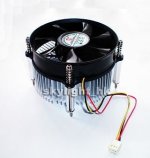
I'd start with four FDA59N30 MOSFETs on each heat sink and go from there. You can use a thermocouple on the rear metal plate (thru the heat sink) of one of the hottest MOSFET to see how well the heat sink is working. Be sure to wait until the heat sink has reached thermal equilibrium first, several minutes. This will tell you if you need to add additional heat sinks, a more efficient heat sink, or perhaps higher fan speed or different fan mounting.
Power limiting...a tough one.
There are analog multiplier chips out there that can take two voltages (in our case, pack voltage and shunt voltage) and multiply them to give you a power level representation, but you often need a lot of circuitry to put it all together (getting right voltages for multiplying, etc.). It gets complicated very, very quickly. I recommend using a microprocessor to read a stepped down pack-voltage and the shunt voltage to calculate the power level. Even a small 8-pin PIC like the 12F683 will work here. It has four 10-bit ADCs, a comparator, and can off the available +5V.
Using the temperature measurements mentioned above, you'll be able to sample the power level several hundred times a second and keep the power level low enough to prevent overheating. Lots of really good temp measurements will allow you to have a much higher starting power level, when the heat sink is cool. This is what I did for my CC-400 load. It handles up to 500W for 15 seconds and then 400W continuously after that. If those limits are exceeded, I turn off the MOSFETs and blink a red LED.
But, any power limiter will require a method of setting it for the different heat sink, fan, and MOSFET combinations other users will have. You could set up a block of header pins with a jumper to tell the PIC the max power level it should allow (perhaps in 25W increments?). But, this would require the user to measure their MOSFET temperature for the setup they have and that's very, very problematic. I don't think that many people are going to drill a hole in their heat sink and get a thermocouple to measure the temp.
I was thinking that in order for the design to be the most useful to others, it will need to be tested with a commercially available heat sink that others can buy. That way no temp measurements need to be taken and they will know the power level allowed by that design. If someone feels they need more power, they can build more units or find a better heat sink.
I'll dive into the schematics soon (still recovering after the fire...sheesh) but wanted to address your MOSFET questions.
You won't be able to use a single TO-220 case MOSFET for dissipating 250W.
Even assuming an infinite theoretically perfect heatsink, you're limited to about 87W.
Here are the numbers:
FDA59N30 junction-to-sink thermal resistance (theta-js) = 1.27 degrees-C/W
Max ambient = 30C.
Max allowable temp rise = 110C (for 140C max junction temp, for reliability).
Allowable power = 110/1.27 = 86.6W before you reach max junction temperature of 140C
If you factor in the thermal resistance for a REALLY good heat sink, let's say 0.15 degrees-C/W, you get a theta-ja = 1.27 + 0.15 = 1.42 and a max power limit of...
110 / 1.42 = 77.5W before you reach a junction temperature of 140C
Even of we made the design pretty unreliable, with a max allowed junction temperature of 175C, the max power level is...
140 / 1.42 = 98.6W before you reach 175C
You'll need more MOSFETs to lower the thermal resistance.
Let's assume four MOSFETs are being used and calculate the required heat sink thermal resistance needed to keep the junction temperature below 140C at a power level of 250W...
Theta-js for four MOSFETs = 1.27 / 4 = 0.318 degrees-C/W
Mac ambient = 30C
Allowable junction temp rise = 110C
Theta-ja = max junction-to-ambient thermal resistance
250 = 110 / theta-ja
theta-ja = 0.44
This means that the maximum allowable combined thermal resistance for the MOSFETs and heat sink = 0.44 degrees-C/W. Since the four MOSFETs theta-j-s = 0.318, then the heat sink's theta-sa cannot exceed 0.44 - 0.318 = 0.122 degrees-C/w. That's a darn good heat sink, but doable!
I'd start with four FDA59N30 MOSFETs on each heat sink and go from there. You can use a thermocouple on the rear metal plate (thru the heat sink) of one of the hottest MOSFET to see how well the heat sink is working. Be sure to wait until the heat sink has reached thermal equilibrium first, several minutes. This will tell you if you need to add additional heat sinks, a more efficient heat sink, or perhaps higher fan speed or different fan mounting.
Power limiting...a tough one.
There are analog multiplier chips out there that can take two voltages (in our case, pack voltage and shunt voltage) and multiply them to give you a power level representation, but you often need a lot of circuitry to put it all together (getting right voltages for multiplying, etc.). It gets complicated very, very quickly. I recommend using a microprocessor to read a stepped down pack-voltage and the shunt voltage to calculate the power level. Even a small 8-pin PIC like the 12F683 will work here. It has four 10-bit ADCs, a comparator, and can off the available +5V.
Using the temperature measurements mentioned above, you'll be able to sample the power level several hundred times a second and keep the power level low enough to prevent overheating. Lots of really good temp measurements will allow you to have a much higher starting power level, when the heat sink is cool. This is what I did for my CC-400 load. It handles up to 500W for 15 seconds and then 400W continuously after that. If those limits are exceeded, I turn off the MOSFETs and blink a red LED.
But, any power limiter will require a method of setting it for the different heat sink, fan, and MOSFET combinations other users will have. You could set up a block of header pins with a jumper to tell the PIC the max power level it should allow (perhaps in 25W increments?). But, this would require the user to measure their MOSFET temperature for the setup they have and that's very, very problematic. I don't think that many people are going to drill a hole in their heat sink and get a thermocouple to measure the temp.
I was thinking that in order for the design to be the most useful to others, it will need to be tested with a commercially available heat sink that others can buy. That way no temp measurements need to be taken and they will know the power level allowed by that design. If someone feels they need more power, they can build more units or find a better heat sink.


