13s4p voltage sag - problems and questions

dougcullen

10 mW
Joined
Apr 20, 2016
Messages
30
Location
New York
Hello,

I'm looking for input into my first battery building attempt:

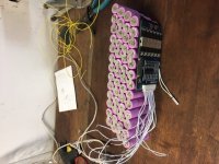
52 cells, 13s4p, brand new Samsung 26F's

Attached pic shows BMS but, BMS got fried during installation, so I'm running this with no BMS, using cycle satiator, and CA3

Series connections are doubled with pure nickel strip. After opening up the pack again, 1 or 2 of the doubled series connections were found to have imperfect welds, but the rest are solid.

Pos and neg 12 AWG leads are soldered across all 4 cells.

My main issues seem to be voltage sag, at 48-49V charge, and full throttle, voltage is going down to about 40V. I'm limiting the power output via CA to 750W.

After about 15 minutes of riding voltage starts dropping, i'm hitting the LVC cutoff, and the CA is going to the home screen.

1000W 9C motor kit from Grin.

I just re-soldered the positive and neg leads with new 12 AWG wire....what might cause this large voltage sagging ? Resistance correct ? But I can't figure out where that might be coming from.

Thanks !
 

Attachments

  • battery1.JPG
    battery1.JPG
    60.9 KB · Views: 935
What did you weld those with? I'd be sketched out unless you used a cd welder after seeing how crappy my 709A performs on pure nickel. Also, for those couple bad spot welds you found there are probably several more that are being disguised by their neighbors as those neighbors continue to hold the strip down. So your nickel strips may be less well connected than you think.

Also, you have 4p and those cells are only rated for 5 amps. I don't know what the voltage discharge curve looks like but wouldn't be surprised if they drop a lot of voltage at that discharge rate, which you would be getting close to at 40 volts / 750 watts on CA.

Also, pic of the lead attachment and what connectors are you using?
 
Thanks Flat Tire,

I also used the 709A ! The welds seemed solid, the nickel was adhered firmly to the poles of the batteries... (except for those 2 i just found ; ) )
It definitely took quite a few weld attempts to get certain strips to stick.
This is the 220V version of the 709A.

Yes but at 48V of charge, and 750W, each parallel group would be drawing 15.6 amps which seems fine ?

Here's some pics of the two lead attachments, kapton non-static tape.....I'm using 30A anderson connectors.

How much voltage sag is healthy ?
 

Attachments

  • battery 7.JPG
    battery 7.JPG
    60.4 KB · Views: 923
  • battery8.JPG
    battery8.JPG
    65.4 KB · Views: 923
^ THIS, and also
- Do you know the specs of your 26F cells ? What resistance do they have ?
- 12AWG is on the small side especially if it's long, being 5.2 milliohm per meter.
- Pure nickel ok, but what thickness et width are they ? It does influence resistivity : https://endless-sphere.com/forums/download/file.php?id=205413

For exemple a 5mm x 1 mm pure nickel stip is 140 milliOhms per meter as you can see from the table.

Loose connections in spotwelded nickel is a good possibility? Check this too !
 
Now that the battery is unwrapped and I had it on the charger for about 30 minutes, I'm noticing that the positive ends of two of the cells in the middle of the pack are very hot !!
I guess i just found the points of resistance ?
 
Thanks eTrike -

This is a 35A controller from Grin. For unknown reasons, the max current feature is hidden on my CA, which i'm working on solving through the programming cable hooked up to my mac, so far no luck with that.

However, isn't limiting the max wattage to 750 on the CA the same as limiting the controller's current draw from the battery ?

What are blowouts ? Is that when you see visible sparking during welding ?

Those hot cells may have poor welds / increased resistance right ?
 
Yes we def burned a few strips through repeated welding when they weren't welding properly. Also at one point a strip was place in the wrong location and caused that nickel strip to turn red hot right away and almost start a fire. Nickel strips are pure.
 
Matador -

Specs on the 26F's --- resistance is listed at 0,09 ohms.

Nickel strips are .15mm x 7mm

Leads are about .3 m long

Thanks
 
A 26F cell has a max rated discharge of 2C, at which point it will sag ~.4V. For a 13s4p pack, you should not exceed 20A, at which point the pack will sag ~5.2V. It's not a good choice of cells for a 10ah battery pack with more than a 20A max controller. It will best operate at 1C discharge, 10A.
 
Back
Top