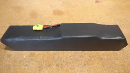
14S4P in linear configuration - BMS balance and Copper/Nickle sandwich

bonbond

1 mW
Joined
Sep 5, 2020
Messages
17
Hi all

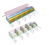
I'm planning a battery build that requires the cells to be laid out linearly.

Like so:
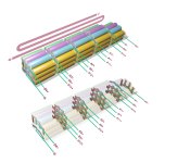

LinearBuild.jpg

I know this layout is a pain and not ideal, but its the only way they'll fit in the cavity...

NB: I'm not planning on building this myself, hopefully getting it build professionally, so just doing my research for fun really and I guess as a backup in case the pro-build falls through.

The plan is to use 56x Samsung 50E 21700 cells, on a Bafang build, which is capped at 30A.

I've got a few questions really, just wondering if anybody can chime in:


  • First of all, have I understood correctly where the BMS leads, B+ through to B-, should attach?
  • Attaching cells end to end like this obviously required them welded side by side, then folded over (exaggerated with u-shapes in diagram). Has anybody build a simple 'folding jig', to keep them all nicely inline?
  • I've read a bunch of really interesting stuff on this forum about copper/nickel-plated-steel sandwich for the welds, can anybody suggest the right copper and plated steel specs for this build?

I've got a ton of other questions, but that'll do for starters :lol:

Thanks!
 
bonbond said:
  • First of all, have I understood correctly where the BMS leads, B+ through to B-, should attach?

Actually it is other way:
-B +B1 +B2 +B3 ....+B12 +B13 +B14=+B

Also IMO:
Code:
3--4  9--10
2  5  8  11  14
1  6--7  12--13
is easier than
Code:
11--12--13--14
10--09--08--07--06
01--02--03--04--05
but unfortunately not better, if cell replacement is required
 
If you’re passing current through 4 connections and need 30amps max current, your series connections are carrying 7.5A each. 10x0.15mm nickel strip will handle that load and is easy to work with. You could use 0.1mm copper sheet the width of 4 cells if you want, but it’s probably overkill.

With just 4 cells per P group to manage, the folding can be done by hand/eye, and will come out fine.
 
v85 said:
bonbond said:
  • First of all, have I understood correctly where the BMS leads, B+ through to B-, should attach?

Actually it is other way:
-B +B1 +B2 +B3 ....+B12 +B13 +B14=+B

Also IMO:
Code:
3--4  9--10
2  5  8  11  14
1  6--7  12--13
is easier than
Code:
11--12--13--14
10--09--08--07--06
01--02--03--04--05
but unfortunately not better, if cell replacement is required

Cheers thanks for that, so (same snaking layout) like this with the balance leads?
LinearBuild2.jpg

and this layout presumably means I'd need to be careful of shorts here:
Insulation.PNG
What would be the best way to insulate against that?
 
From-A-To-B said:
If you’re passing current through 4 connections and need 30amps max current, your series connections are carrying 7.5A each. 10x0.15mm nickel strip will handle that load and is easy to work with. You could use 0.1mm copper sheet the width of 4 cells if you want, but it’s probably overkill.

With just 4 cells per P group to manage, the folding can be done by hand/eye, and will come out fine.

Thanks, so there is only 7.5A between each cell, that load is uniform all the way through the pack (sorry for noob question)?

I was thinking about sandwiching copper between the cells and the nickel-plated-steel for all the series connections, I've read some fascinating stuff on this forum about welding copper with this method. As I understand it, resistance isn't a concern the parallel connections?
 
bonbond said:
From-A-To-B said:
If you’re passing current through 4 connections and need 30amps max current, your series connections are carrying 7.5A each. 10x0.15mm nickel strip will handle that load and is easy to work with. You could use 0.1mm copper sheet the width of 4 cells if you want, but it’s probably overkill.

With just 4 cells per P group to manage, the folding can be done by hand/eye, and will come out fine.

Thanks, so there is only 7.5A between each cell, that load is uniform all the way through the pack (sorry for noob question)?
Short answer is yes. It'll be uniform if the cells in each parallel group are of same capacity, if they are of same or similar IR, if they are balanced. And if all the series connections (4 strips of nickel in your case) are of equal resistance. If you sourced, sorted, and balanced your cells correctly, built correctly, then yeah, load is uniform at the series connections.

A bad example for learning: say you have 2p, one cell has a capacity of 3000mah, other cell has a capacity of 1500mah. You draw 15A from these cells. The 3000mah cell, at twice the capacity, will also be responsible for twice the amperage. 10A drawn from 1 cell, 5A drawn from the other. Meaning that the connection between that 3000mah cell and the next one in series will be carrying twice as much current as the nickel strip next to it. Hopefully goes without saying: don't do this.

bonbond said:
As I understand it, resistance isn't a concern the parallel connections?
It's not, not a concern. It's just that the current is flowing primarily between the series connections during charge and discharge. The parallel connections are there to help the cells stay in balance, which does see current, just not nearly as much compared to the series connections.
 
Hi Bonbond,

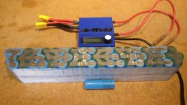
I googled your username and saw you're building an E22 frame. I thought I'd let you know of another 14S4P 21700 cell configuration that fits in that frame. There is slight compromise in the series connections but it is much easier to build. This is my first battery build with great help from this forum along with 20 years experience working with electronics.

I used 0.2 mm pure nickel with kapton tape between each parallel group and neutral cure silicone.
IMG_20220429_211442.jpg

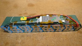
I used a 30A Bluetooth BMS. Every wire is isolated from the cells with either kapton tape or fishpaper
IMG_20220501_162700.jpg

The top and bottom are covered with adhesive fish paper wide enough to wrap around the sides. This made the pack very stiff.
IMG_20220501_165332.jpg

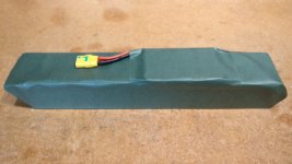
I used polyolefin heat shrink tubing. Expensive but tough.
IMG_20220506_183946.jpg

In the frame.
PXL_20221121_215112687.jpg

Trust me that the cover fits.
PXL_20221121_215106507.jpg

I still need to design a cradle and retaining mechanism. I was going to strap it to the cable management clamps but I'm not sure the carbon fiber can take that much stress at the threaded inserts.
 
Back
Top