150v 35amp FDP2532 mosfets X-Lite Controller

steveo

100 kW
Joined
Oct 6, 2007
Messages
1,786
Location
Woodbridge, Ontario
So i bought one of these off the forums .. that had been modified my fechter with the FDP2532 mosfets..

I was told there is a heat issue with the controller at higher voltage ..I'm thinking watercooling or fan cooling the controller..and sodering 2 of the shunt wires to get more amps out of the controller.

I haven't tested it with load yet .. maybe on the weekend.. but my question is does anyone forsee any problems operation @ 133v.. on my 20" 5304? ... i'm looking to get 80 km/h out of my bike ..

My bike @ 100v on a 2p 3s dewalt pack .. hit close to 70km's.. so i know the extra 33v will be what i want ..

I know i could go faster if i just got a 26" ... but i must admit i love the low end .. so i'm keeping it as is ..

i'll be using a 26" on my 2nd build..

Your thought guys!
-Steve
 
Go for it.

I think if you get good air flow over the controller and the outside temp is cool, it will fly. You could add some fins on the bottom of the controller (or at least the side that has the heat sink screws all over it). I thought about using pieces of aluminum U channel screwed to the bottom to make fins.

It's the current that causes heating, but at those voltages and speeds, the controller might be at the current limit most of the time.

It should be no problem for short runs, but watch the controller temp over time.
Your batteries might discharge before you run into a problem.
 
Yes, low end is what really gives you a sense of power. Can't do away with that 8).

Other thoughts is that 80km/hr is going to be easier on the system @ 132V and a 20" than at 99V and a 26". You'll probably go faster than just increasing wheel size, too.

A heat sink stuck to the side of the thing might help, too. Something like a small CPU sink proabably would work very well, assuming you could power the fan.
 
I think I read in here that these hub motors are more efficient at higher RPMs too. So another reason to keep the smaller wheel. Just a reminder, if I'm not mistaken, 133 VDC qualifies as lethal dosage. We had a discussion once and I can't remember the breakpoint. Of course, any current has no advantages for us to take and 100VDC probably has the potential as well.
 
I'll work on the controller on the weekend... i will repast the mosfets so the paste is fresh & thermal contact is good. .. i'll give it a no load run & let you know how it works out :D

-steveo
 
I was able to run this controller today ..

I never ended up opening the controller .. all i did was run 100v on a 2p 3s pack .. and the results... stock shunt..

The controller can crank about 40 amps no problem even though its a 35amp controller.. .. I was able to bring my bike to a very very very steep hill and the bike took the hill like it wasn't even there.. i still can't believe the preformance of an x5 at 100v .. on a 20" .. its incredable! .. The torque on low end isn't like my other controller which is good.. I was having a hard time keeping the front wheel on the floor before .. this controller has enough .. I will be using my 4110 controller on my 26" build where the sodered in shunt will have more use for ..


Next will be 133V on the 150v controller ..
:twisted:
-steve
 
At higher voltages, the current has a tendency to increase a bit. Certainly there will be higher motor current at low speeds. Doesn't that one have a current limit adjustment knob? (can't remember)

How's the controller heating? You might not have any issues with the smaller wheel size since you can only draw so many amps before the bike throws you off :twisted:
 
One note ... with heatsink paste, using too much is equal to adding insulation. In fact, factory techs almost always add way too much. The metal surface should have a small amount rubbed on, and the excess scraped off with a razor blade ... just a paper thin coat.


My $0.02:

Get some thick aluminum sheet ... bend the last half inch or so, remove paint from the side of the controller, add a thin coat of heat paste, and screw it to the side of the controller using the same bolts that hold the FET heatsink to the inside of the controller.

Saw perpendicular slots into the side of the sheet of aluminum if that isn't working fast enough.
 
fechter said:
At higher voltages, the current has a tendency to increase a bit. Certainly there will be higher motor current at low speeds. Doesn't that one have a current limit adjustment knob? (can't remember)

How's the controller heating? You might not have any issues with the smaller wheel size since you can only draw so many amps before the bike throws you off :twisted:

This one does not have current limiting knob .. its an old 36v - 72v controller 35amp shunt

I haven't overheated the controller .. Keep in mind its still winter here .. probably -1 - -5 est temps when i brought it out yesterday .. I brought the bike to a very very very steep hill i wish i had done a video ... must of been drawing 40 amp for about 45 seconds.. ran fine!!!!

the controller with a stock shunt i think is enough power for the wheel size .... low end is fine .. 133v is comming for more speed.. :).. as i've said with my 4110 mosfet controller . with sodered shunt.. the bike throws me off litterly ..
with the 150v controller .. i can still wheelie .. but if i push my weight forward .. i can full throttle it .. and have a little wheelie but get a nice acceleration start..

-steveo


-steve
 
kbarrett said:
One note ... with heatsink paste, using too much is equal to adding insulation. In fact, factory techs almost always add way too much. The metal surface should have a small amount rubbed on, and the excess scraped off with a razor blade ... just a paper thin coat.


My $0.02:

Get some thick aluminum sheet ... bend the last half inch or so, remove paint from the side of the controller, add a thin coat of heat paste, and screw it to the side of the controller using the same bolts that hold the FET heatsink to the inside of the controller.

Saw perpendicular slots into the side of the sheet of aluminum if that isn't working fast enough.

If i have heat issues it will be my next step ... but doesn't shorting the fet involve it making direct contact with the aluminum heat sink & screw or no? ... isn't that the reason why when we screw the fets in its importat to insulate the screw to avoid the fet making contact with the aluminum and the aluminum contacting another fet and shorting it ?

-steve
 
fetcher just wondering if you've posted mods needed to use 150v fets?

also I got some high speed switching controllers will be testing on bmc 500watters shortly ( 24v-100v 40amp) might resolve that issue folks have been having
with 500watters 'missing' at higher rpm
 
solarbbq2003 said:
fetcher just wondering if you've posted mods needed to use 150v fets?

also I got some high speed switching controllers will be testing on bmc 500watters shortly ( 24v-100v 40amp) might resolve that issue folks have been having
with 500watters 'missing' at higher rpm

Actually, the pics in the Crystalyte Modification thread are of the 150v controller that Steveo has. :wink:

I'll be very interested in the new controllers. The Puma and BMC use the same winding configuration.
 
Since I had overheating problems at "only" 96V with that, and sometimes even at 72V if it were really hot, I'd recommend going on many long rides with it as it is to make sure it behaves itself before you increase voltage, steveo. But it's true that higher voltage would mean less current needed.

The heatsink is a good idea. I had opened up the two ends a bit so air can pass directly through, but this isn't necessarily as effective as a heatsink whose fins are parallel to the forward axis (you need wind to blow along the fins). Might as well go with the heatsink idea just because it can only help.
 
steveo said:
If i have heat issues it will be my next step ... but doesn't shorting the fet involve it making direct contact with the aluminum heat sink & screw or no? ... isn't that the reason why when we screw the fets in its importat to insulate the screw to avoid the fet making contact with the aluminum and the aluminum contacting another fet and shorting it ?

-steve

My clyte controller has the aluminum case screwed directly to the heatsinks on the backs of the FETs.

I think you need to avoid shorting the case against the legs or the solder joints on the FETs.
 
How can you comment on the differences you're seeing between the 4110 controller and this one? And how many amps should you be able to run this at?

Someday I might be interested in switching to a 150v unit instead of my 4110 unit. The question is under what circumstances it would be worth it.
 
fetcher any chance you could do a list of components that need to be changed on analog crystalyte controllers to run on 150v?
 
Just FETs and capacitors, if I'm not mistaken. Everything else is on the low voltage side, fed by a voltage regulator.

Also, you'll need to make sure that your CA can handle it. It will blow above 115v if it isn't a 200v unit. I don't know what exactly is involved in that bit, but you can send it in for that upgrade. Justin quoted me $45 labor on it.
 
On the one shown in the Crystalye modification thread, the stock capacitors (the big ones that are glued down along the edge of the board) were already rated for 160v, so I figured they were good to go.

Other than that, just the FETs need changing. Nothin else. The voltage regulator pass transistor is rated for 400v, so no worries there.
 
ok thanks for that,
to get the heat down, puting additional mosfets would require drivers for each fet?
 
Not sure about that. You might be able to drive additional FETs with the same driver. Each FET should have its own gate resistor. The gate charge for the FDP2532 is much lower than a IRFB4310, and those have been used successfully, so I'd guess you could possibly drive 4 FDP2532's with the existing drivers.

It would be good to check the gate signals with an oscilloscope if you try it. If the gate driver is too wimpy, the switching speed will be too slow, and the switching losses will go up, causing heating. In an extreme case, it could cause shoot-through, but I doubt that would happen.

Stuffing the extra FETs into the case would be challenging.

One other thought: Since there are always two high side switches on at any given time, against one low side switch, you could double up on the low side FETs only. This will drop the heating. Since the low side FETs switch at a much lower frequency, the effect of slower switching speed will be minimal.
 
ok excellent info, excuse my lack of knowledge on this but how do you distinguish high and low side fets?
and what is 'shoot through'? fet just stays open?
 
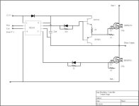
Here's the output stage for the old analog type controllers. The new ones are similar.
Each phase wire can be switched to either the battery + (high side) or battery - (low side).

If both switches are on at the same time, it short circuits the battery. This is shoot through.
A shoot through will generally destroy one or both FETs instantly.
Brushless Controller Output stage.jpg

The idea of doubling up the FETs is interesting. You might be able to take a second FET and just solder the legs directly to the legs of the existing FET. You could find an aluminum spacer the same thickness as a FET and place it between the two FETs. Since the tabs are connected anyway, no insulation would be needed on the spacer. Then all you need is longer mounting screws to fit through both FETs. The screw needs to be insulated. The whole board would be raised up by a FET thickness, so you'd have to use a spacer on the voltage regulator transistor to even out the board. Not sure if everything would still fit in the case?
 
The whole board would be raised up by a FET thickness, so you'd have to use a spacer on the voltage regulator transistor to even out the board. Not sure if everything would still fit in the case?

It would work well in the v2 controllers, at least physically. Would the drivers be able to handle doubled FETs all around in the v2 units?
 
Back
Top