18650 spot welding -how to- ULTIMATE REPOSITORY

Alan B said:
okashira said:
Alan B said:
Does anyone know of any success examples with copper? I have seen a lot of attempts and failures. Can we find any examples of success?
Sunstone's pulse arc welder would work great for copper.

So what are the requirements for successfully welding copper?

I saw people mentioning 25-35V, and 600J, but that to me seems to much. My max weld energy is 200J when using 20V / 1F but that's quite a lot.
 
that's total system energy at 20V?

Ive been able to weld 0.15 copper @ 3200 amps or so with 20ms pulse. About 9V. Copper must be split to force current through the joint.
That's about 570 Joules of total energy, but only about 140 of which occurs at the actual weld.
Even then it's not mechanically strong.
 
okashira said:
that's total system energy at 20V?

Ive been able to weld 0.15 copper @ 3200 amps or so with 20ms pulse. About 9V. Copper must be split to force current through the joint.
That's about 570 Joules of total energy, but only about 140 of which occurs at the actual weld.
Even then it's not mechanically strong.

thanks for the info.

yes that's my total system energy @20V / 1F.

I just tried also with rounded up molybdenum electrodes. That stuff is seriously hard, took me 10 minutes to polish and unsharpen tips using sanding paper and a drill. Same non satisfactory results when welding copper.

What's your system?How many Farads? what electodes are you using? Is it double pulse for copper? p1, and pause? How hard do you press when welding?

thanks
 
I have had some good experience with copper. I built a 20s5p pack for current flow of up to 60amps.
It took a lot of faffing around to get started, but this is what worked
Home built transformer based spotwelder ( initially a MOT then bigger- bigger was much better, the MOT struggled)
Copper electrodes (anything else stuck like bug grey)
Slotted tabs
Clean smooth surfaces
.1x8mm copper (pure, not plated)
I put a P layer of nickel strip (.15x8mm) down to join and protect the cells ( from the inevitable blowouts)
Then I welded the copper S connectors to this. It's more difficult than nickel welding and weaker. If I tested the welds to firmly the copper would tear.
Tungsten (tipped) electrodes are apparently the bees knees but I didn't have the power to drive them. If you do, then the resistance of the W heats and welds the copper. RTL had great success with this method. For me, with W electrodes, I had unbelievably good welds... of the electrode to the work piece :shock: , such that I would have to tear it off with such force as to destroy the tab and can.
Short high amp pulses are the key. And repeatability. Hand held electrodes would be tough bc of the inconsistency.
Slow going but makes for good current flow...
K
 
That is a good new kdog,

I am building a big Panasonic cap bank of 2.8Farads 35V total with less than 100 microohm Ri and will use thungsten electrode. I also plan using 0.005" copper strip.

I will post build progress and weld test result.

I am actually cutting the large 0.020" copper sheet that will link each of the 3x 23 caps POS and NEG in parallel for total 66x 47 000uF caps.

Doc
 
Doctorbass said:
That is a good new kdog,

I am building a big Panasonic cap bank of 2.8Farads 35V total with less than 100 microohm Ri and will use thungsten electrode. I also plan using 0.005" copper strip.

I will post build progress and weld test result.

I am actually cutting the large 0.020" copper sheet that will link each of the 3x 23 caps POS and NEG in parallel for total 66x 47 000uF caps.

Doc

which caps are you using to build the cap bank?
 
vex_zg said:
Doctorbass said:
That is a good new kdog,

I am building a big Panasonic cap bank of 2.8Farads 35V total with less than 100 microohm Ri and will use thungsten electrode. I also plan using 0.005" copper strip.

I will post build progress and weld test result.

I am actually cutting the large 0.020" copper sheet that will link each of the 3x 23 caps POS and NEG in parallel for total 66x 47 000uF caps.

Doc

which caps are you using to build the cap bank?


As i said: 60x Panasonic 35V 47000uF and measured Ri of 6 miliohm each.

All pos parallel and neg parallel connected with each a thick copper sheet all over the cap bottom.

Doc
 
You'll need more than 6v to drive big amps through the resistance of the W electrodes. I would think 10-12 would be good, maybe less with good quality electrodes. I was using TIG electrodes with a copper sleeve to the tip ~3 mm of W sticking out. At 2v (mot) it was hopeless- a metal warming device. At 6v (bigger Tfmr) it welded but stuck so bad I couldn't use them. RTL's welder made the tips glow red hot for a split second helping weld the copper- not sure what voltage his outputs ( dn10).
K
 
Doctorbass said:
vex_zg said:
Doctorbass said:
That is a good new kdog,

I am building a big Panasonic cap bank of 2.8Farads 35V total with less than 100 microohm Ri and will use thungsten electrode. I also plan using 0.005" copper strip.

I will post build progress and weld test result.

I am actually cutting the large 0.020" copper sheet that will link each of the 3x 23 caps POS and NEG in parallel for total 66x 47 000uF caps.

Doc

which caps are you using to build the cap bank?


As i said: 60x Panasonic 35V 47000uF and measured Ri of 6 miliohm each.

All pos parallel and neg parallel connected with each a thick copper sheet all over the cap bottom.

Doc

sorry I must be going blind and haven't read your original post through. Those panasonics are discontinued and can't find them anywhere. Do you have a source to recommend?

I saw in their specs that they are 6cm x 4cm so 66x of them will take quite some space. But very low ESR.

What cables would you use? I would presume 2/0 or 4/0 AWG if you want to be in sub 1mOhm total resistance.
 
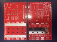
Hi guys I was able to get the files for these loaded to osh park.
http://www.instructables.com/id/DIY-Arduino-Battery-Spot-Welder/step3/Populating-the-PCBs-and-adding-wires/


So any of you who want to order a set of 3 boards here is the link.

https://oshpark.com/shared_projects/cT1nnc6l
 
Arlo1 said:
Hi guys I was able to get the files for these loaded to osh park.
http://www.instructables.com/id/DIY-Arduino-Battery-Spot-Welder/step3/Populating-the-PCBs-and-adding-wires/


So any of you who want to order a set of 3 boards here is the link.

https://oshpark.com/shared_projects/cT1nnc6l

Thanks a lot for doing that. I just ordered a couple of boards from a guy on the Instructables site, but this link will come in handy for others I'm sure. Maybe once we get a few of these 'out in the wild' we can report back here and see how they are working out. I will share my experience for sure.
 
My plan is to use the most bad ass fets I can find and push this thing to its limits!
As always :)
 
induna said:
Arlo1 said:
Hi guys I was able to get the files for these loaded to osh park.
http://www.instructables.com/id/DIY-Arduino-Battery-Spot-Welder/step3/Populating-the-PCBs-and-adding-wires/


So any of you who want to order a set of 3 boards here is the link.

https://oshpark.com/shared_projects/cT1nnc6l

Thanks a lot for doing that. I just ordered a couple of boards from a guy on the Instructables site, but this link will come in handy for others I'm sure. Maybe once we get a few of these 'out in the wild' we can report back here and see how they are working out. I will share my experience for sure.

does that spot welder offer some adjustability of pulses/voltage/energies?

i built my CD welder around arduino uno + 4x20 character display so it's easier to set up and program to do whatever you want when you have a big LCD to see what's happening. I could't find a good enough open source version so wrote my own.

I will also try to add during-the-discharge monitoring so I can set pulse energies instead of pulse lenghts. Not sure if arduino is fast enough for that.
 
vex_zg said:
induna said:
Arlo1 said:
Hi guys I was able to get the files for these loaded to osh park.
http://www.instructables.com/id/DIY-Arduino-Battery-Spot-Welder/step3/Populating-the-PCBs-and-adding-wires/


So any of you who want to order a set of 3 boards here is the link.

https://oshpark.com/shared_projects/cT1nnc6l

Thanks a lot for doing that. I just ordered a couple of boards from a guy on the Instructables site, but this link will come in handy for others I'm sure. Maybe once we get a few of these 'out in the wild' we can report back here and see how they are working out. I will share my experience for sure.

does that spot welder offer some adjustability of pulses/voltage/energies? .
yes uses arduino and a simple display cheep to build easy to use
 
18 pages and I bet I missed it on page one..

How are you setting your welders? I have just received a 788+ and will be getting some 0.15 strip maybe 8mm wide. The welder has a number of controls. What would be a good starting point?
 
i have the knob set 5~7 and the pulse 4 and 8 button pressed.
 
Thanks Flippy
I'm sure that will make sense when I see it :)
 
I made this calculator for a mosfet type welder and for batteries (specifically JP welder + battery source)
I put a good amount of work into it, so please give credit and keep my contact on there if you modify it. And distribute this read only link.
https://onedrive.live.com/redir?resid=6 ... ile%2cxlsx

Make sure you update the blue values to match your setup. Green values i carefully tweaked based on lots of testing and data... but if your setup is different keep that in mind

One could tweak it to work with a cap welder (hint, major change in the % peak current column is needed - you need to account for the falling voltage of the capacitors based on coulombs discharged) let me know if you need help with that. I spent about 15 minutes giving it a start... added calculated voltage drop @ the cap, now you need to use this to compensate for new voltage and how it will affect the current slew rate and peak current ...

Nobuo can you put in OP?
Would like to see someone develop it more for a cap welder.
 
I have some of the Arduino car battery DIY boards from PCB - I'll post them in the Items for sale - new section. http://www.instructables.com/id/DIY-Arduino-Battery-Spot-Welder/

I'll swap a board for four MCP 14E10-E/P or give one free to the first person that tells me how to get the MCP 14E10/E-P locally in Australia or without paying stupidly high postage fees.
 

Attachments

  • image1.JPG
    image1.JPG
    72.2 KB · Views: 2,267
Hey guys,

I am just curious, why are most using 7mm wide strip instead of 10mm?
Is there any particular reason for this. I wish for max conductivity and I guess the wider the better for that. As the cells are 18650, 10mm should not be a problem at insulation.
Also when I need even more amp at the end of the two end point parallel series, is it a good idea to just spot weld a few levels more on top of the first layer, or is it better to solder braided flat copper to it?
I know going 0.2 thickness is an option, but I have no idea what my home build spot welder can do for max.
I hope the question makes sense :)
Thanks for the help

Cheers
Alex
 
10mm wont fit any of the cell holders.

Ps: tats, i can ship them to you for about 6~10 euro shipping an i can buy them for about 2 euro a piece and ship them In a regular bubble envelope.
 
flippy said:
10mm wont fit any of the cell holders.

Is that all? Good. I don't use any cell holder. My application is purely FPV model airplanes. So space always needs to be maximized.
Hence packs are tight as possible. I do put a little bit of hot glue in between. The thing to know is in this application we are not susceptible to constant and strong jerking motion, unlike a bike or skate.

See example of what I mean by spacing I use. This one I soldered (before I got spot welder). However I am having a hard time finding 0.15 x 10mm strips that are really pure nickel. Everyone is selling plated steal. :(
All I find is 0.7. So do you think it could be a good solution to weld two layers to increase max amp?

Pw4TsjE.jpg


0eUQGOv.jpg
 
Back
Top