2008 CRF250R - QS138v3 70H - ANT - Sanyo UR18650-RX 20s20p - Votol EM260

bananu7

10 mW
Joined
Sep 27, 2024
Messages
30
Location
Poland
This build thread might be a bit premature, but since I've already invested countless hours in reading the forum, I figured I might as well start posting before it begins. Long story short, I want an electric enduro bike, and having exhausted all options for ready models, I found someone selling a half-finished build. The bike has the engine and the controller mounted in, and the battery has been ordered in a reportedly reputable local shop. I'm scheduled to pick it up next weekend if the battery does indeed materialize. Here's what I have laid out so far, please tell me if you spot any mistakes, improvement ideas or reasons not to get into this :)

Just to clarify: I have no experience building electric motorcycles. I've built two ebikes from kits this year, and have amateur electronics and CAD/3D printing experience. I own an EXC500 enduro that I ride in rally competitions as well as superenduro practice and maintain myself. The donor bike is supposedly in good mechanical condition with suspension serviced and all bearings replaced, but I can deal with any issues on that front if they arise.

Now, since this is a project that's been already started by someone else, I am a bit locked into the choices made here. That being said, I think it fits my needs quite perfectly. What I ideally want to build:
- under 100kg total
- not competition, just for recreational riding
- mostly enduro/hard enduro/trials - low speeds
- likely with almost no plastics to not look too conspicuous near friendly monster e-bikes
- safe to ride and charge

Mechanically I plan to put the rear brake on the handlebar, potentially with switch wired from it to regen braking as well, original 21/19 wheels with stock tyre sizes. I'll likely replace both master cylinders with a matched set if I can find something decent for a reasonable price. I don't really need a screen, but might make a simple arduino bridge to the CAN/serial output to get voltage and error status from the controller and show it in a discreet way.

As for target power: given the cells are rated at 16.6A cont. / 21.2A peak, this would give me figures of 332 and 424 amps, respectively. That being said, I've seen factors of 50-80% being applied to 18650 cells in a pack, so let's settle on 200 continuous and 350-400A peak. At the rated 72V, it's 14.4kW of continuous power, potentially as high as 32kW in few-second bursts; at least that's what the battery should be able to sustain. I don't expect the small 70H motor to last an hour at 14.4k, but given I'll mostly be doing trail riding with occasional logs and steep uphills with plenty of cooldown in between, i am not very concerned about that. The controller is supposedly rated at 190/450A, so my target settings for this, considering Votol software, would be 200A for normal busbar current, with modes set probably at something like 25/50/100%, and 350-400A of sport mode current, potentially with the limit timer just in case.

Considering the engine having 1:2.35 reduction, with the stock 13:51 gearing, gives me 9.21 final drive ratio. I still have the option to go to 52 on the rear, but I think it should be quite okay if I can kick in the double power for 15-30s needed for the steepest climbs and obstacles. I have calculated the max speed given reasonable engine RPM to be about 95km/h, and would happily accept 70-75 on the final construction if the low-end is strong enough.

One thing I'm a bit concerned about is the battery capacity. The cells can produce respectable current, but the data online only gives them about 2Ah each. That would mean just 40Ah for the entire battery, or 2.9kWh. That's suspiciously small considering how large the usual electric motorcycle batteries are, and so the battery might need an upgrade in the future - likely to be replaced either with some LG chem pouch cells, or at the very least something like VTC5a which seem to have both higher current and +30% capacity. At least the weight of just the cells comes up at around ~18kg, so that's looking good for my weight target.

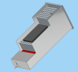
The biggest part left to finish in this project is going to be the battery case, and for that I'm currently aiming at creating a sheet metal design that I'll send to my local aluminium shop, so that they can review it, sent for laser cutting, then bend and TIG weld for me.
1727810718073.png
The plan would be to glue FR4, epoxy fiberglass or PC panels inside to prevent shorting on the box, then cradle the battery inside with some rubber. I'm still not sure how the finish battery will look like, but I'd like to connect it to waterproof outside terminals using either thick copper bars or 0AWG connecting segments. Details of those connections are TBD - as well as how the box will actually close.

So, while i sit here and twiddle my thumbs, here are the questions to the community:

1) Do you see anything concerning in the project based on the above?
2) Is my idea for the box okay? If so
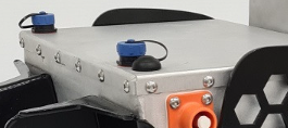
2A) Do you have opinions for how the box should close? A small lid on the top held by screws around it or two halves grabbed together around the perimeter?
1727810994008.png versus 1727811015925.png
3) Should I have a precharge resistor / battery killswitch?
3A) if so, should it be operated completely automatically with a timer to prevent misuse or manually with double switches?
3B) should the contactron for the main circuit reside inside or outside of the battery?
3C) is it okay if I leave the precharge circuit always-on and only switch the main output?
3D) is it necessary to have the main battery killswitch easily accessible? I plan a magnetic killswitch on the handlebar wired to the controller as a safety measure.
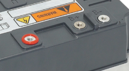
4) Do i need another fuse inside or near the battery? AFAIK the controller has a place for a fuse on its enclosure:
1727810960936.png

Let's hope I can indeed make this project real; at the same time, huge thanks to the community for posting so, so much valuable information here, so I could even contemplate such an undertaking.
 
Last edited:
Still on the road, so very short update, but - the project is finally kicked off. Bike picked up. Battery should be here in a week or two.
1728152652543.png

Adding to the list of questions:
5) How do I fit a 520 sprocket to the 138v3? Nobody has told me it has a 17/14 shaft. Ideally I'd find a solution that allows using regular cheap dirtbike front sprockets, not having to custom source ones for this spline.

I'm actually thinking about switching to the 428 chain. I got a new 520 chain and rear sprocket with the bike, but if 428 ends up strong enough, it's cheaper and lighter, plus super easily accessible, so basically just better.
 
Last edited:
Drivetrain update: after some painful digging for sprockets, I think I found it. I have no idea why JT, superprox etc. only allow searching by make and model and not raw parameters: spline for front and hole size and spacing for rear. Either way, by manually browsing through, I found two matching specimen, for reference:

JTR1258 - from Honda XR125L, 54T
JTR1226 - from Honda XR150L, for more speed - 49T

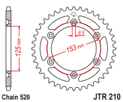
The original one is JT210. Comparing them just by the drawings, seems that the 428 are offset so that the chainline should stay roughly the same, but I am not going to trust those and will adjust with all the parts on the bike. Of course I'm going with the 54T for more torque (~20 eur), which means I now get access to all sizes of 2.5 eur sprockets fitting all kinds of Chinese bikes and mopeds (Kayo, 139FMB-engined mopeds etc.). I'll likely get some proper sealed chain though, because it is going to be a size downgrade for a bike that will be pulling just as hard as a stock 250. DID enigmatically says that their strongest sealed 428 is good up to 350cc, but the price is a bit high.

1728161612682.png
 

Attachments

  • 1728161625349.png
    1728161625349.png
    32.6 KB · Views: 1
As for target power: given the cells are rated at 16.6A cont. / 21.2A peak, this would give me figures of 332 and 424 amps, respectively. That being said, I've seen factors of 50-80% being applied to 18650 cells in a pack, so let's settle on
This should be found out in the official datasheet of the cell manufacturer.
While assembling one of the batteries, I asked what current is offered by LG for its 3.6V 63Ah lithium ion battery packs, it turned out to be only 36A, but the salesmen assured me that it is possible to take 200A from them IMMEDIATELY.
So don't be surprised if after 100 or 200 times of charging and discharging the battery it loses capacity.
Fair! I tried to find a datasheet for them, but only got conflicting information. They have pack considerations, but the current rating remains the same - 20A per cell. I'm assuming that means I'm good up to that as long as I keep them under 60C. I mostly plan to keep the bike in the 200A range with occasional boosts, so I feel reasonably safe here - but a battery temp meter is planned nevertheless.
 
Adding to the list of questions:
5) How do I fit a 520 sprocket to the 138v3? Nobody has told me it has a 17/14 shaft. Ideally I'd find a solution that allows using regular cheap dirtbike front sprockets, not having to custom source ones for this spline.
These guys may have what you are looking for:
Amp Sprockets
 
These guys may have what you are looking for:
Amp Sprockets
Oh, yeah. I should've mentioned I found that, but things are moving fast. Being in Europe, 40 bucks for a sprocket (+ shipping, + customs) just doesn't compute. I'd like the bike to be maintainable, and it seems that switching to 428 will have other benefits. If for whatever reason I won't be able to make that work, I'll try to source that sprocket somehow, in the middle I've ordered a chain and the steel rear 54T.

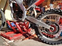
I got the bike safely home, and stripped it partially. Discovered quite a few gremlins, but nothing I can't fix. I had a small panic attack at a frame scratch that looked very much like a crack, sighed at a welded rim and a 4.8 bolt on top of the damper, wiped brake fluid leak... Usual stuff.

So, before I get to replacing every single bolt that looks at me funny, here's how it looked when I got it home.

IMG_20241006_133229.jpg
 
Update for today: made a build sheet and started ordering components that I'm mostly sure about. Decided to try a cheap brembo clutch knock-off as a rear slave first, and to avoid dealing with button switches (or lack of thereof), got a pressure switch assembly:

1728332801024.png
This can go straight on the lever, crucially any lever, instead of the original banjo bolt, and should provide reasonably quick activation. In a pinch, i can also put it on the rear caliper.

TIL that there is more than one version of EM260, and I seem to have the S, not the SP variant; that's why it looked smaller and had terminals in different places. The S version has 690pA, so should still be plenty.

Inspired by J Bjork's laminate covers I started eyeing them up for the CRF; unfortunately, while I have plenty of mounting options, the two top frame nuts sit a bit too far outside for my liking. I'd really like to avoid making the bike more bulky than needed, so I'll need to plan around making the template just barely covering that spot, ideally with a bolt that doesn't protrude too much. All of the materials for GFRP seem readily available here, and I think the easiest for a complete beginner like me would be to go for a regular 150g/m2 mat and polyester resin + gelcoat, and use the mold method (make the mold first then make the actual part in the mold). I'm tempted to try this also because I might consider it as an option for the actual battery cases if the process proves relatively painless.

I also got some more pics of the battery in progress - not sharing since I'm not the one making it, but we're just waiting for a new ANT to arrive. For reference, it's (I think) the biggest one they offer, and the first one just straight up refused to turn on.
 
2) Is my idea for the box okay? If so
2A) Do you have opinions for how the box should close? A small lid on the top held by screws around it or two halves grabbed together around the perimeter?
View attachment 360261 versus View attachment 360262
Small lid on the top seems like a better idea. You should not have to open it very often anyway once your battery will be done.
Condensation is a big issue for battery enclosures, especially if your bike stays outside during the night. You need to plan ahead for this if you can.

3) Should I have a precharge resistor / battery killswitch?
No, personnally I would not use one as it's unnecessary if you get a BMS that does this already. Which seems to be the case since you mentionned you'll be using an ANT BMS.
3A) if so, should it be operated completely automatically with a timer to prevent misuse or manually with double switches?
Unnecessary
3B) should the contactron for the main circuit reside inside or outside of the battery?
Same, a contactor isn't necessary as the BMS can do the same anyway.
3C) is it okay if I leave the precharge circuit always-on and only switch the main output?
Yes, but then it's not great safety wise when you work on the bike as there will be some voltage everywhere so you might fry stuff in case you wrongly connect something while working on it.
3D) is it necessary to have the main battery killswitch easily accessible? I plan a magnetic killswitch on the handlebar wired to the controller as a safety measure.
I would just use the brake signal or maybe the controller ignition wire as the killswitch input. It wouldn't cut all the power to the whole bike, but it would cut the power to the motor which, in my opinion, is enough. A magnetic killswitch on the handlebar seems like a good solution, yes.
4) Do i need another fuse inside or near the battery? AFAIK the controller has a place for a fuse on its enclosure:
Yes, you need a fuse as close as possible to the battery. Something that is installed before anything else is connected to it. Using a fuse on the controller is good, but then if you get a short circuit somewhere in the power leads that lead to the controller then there will be nothing to stop the current. Also, take into account what could happen when the fuse blows, so it doesn't damage some critical components when this occurs (so possibly some heat shielding or at least some clever positioning of the thing, don't put it right in the middle of your cells obviously).

Update for today: made a build sheet and started ordering components that I'm mostly sure about. Decided to try a cheap brembo clutch knock-off as a rear slave first, and to avoid dealing with button switches (or lack of thereof), got a pressure switch assembly:

1728332801024.png

I don't recommend you to use these. I've tried a few and they kept failing. In my experience the traditional switches have been more reliable even though they do fail as well from time to time. The big difference is that when the switches fail they are easy to repair. But when these pressure switches fail you have to take them out and then bleed your circuit again. 5 minutes job vs one hour job.

I mostly plan to keep the bike in the 200A range with occasional boosts


200A might be a bit weak, you should probably try to target at least 300 for a motorcycle, if possible. I think you said you were gonna use a votol controller but you didn't say which one. I'm using a votol EM150, supposedly good for 150A, but mine is actually set up so it takes 330A from the battery and it doesn't seem to complain about it, so just know that you have some good margin to play with it if you need.
 
Thanks for the detailed response! I'm not going to quote reply to everything but:
- I'll try to read more about the ANT BMSes; I thought they can act as a switch, but I wasn't sure if that's enough to prevent too much inrush anyway
- I'll wire the magnetic switch to controller killswitch not battery killswitch, makes sense
- A fuse inside of a battery seems reasonable then if I can open the case
- The pressure switch failing would be unfortunate indeed. Maybe it's just the cheap ones, though? My big KTM has one on the foot brake and it's been dead reliable for the last 13 years.
- I'm trying to keep the current ratings conservative for safety. In enduro riding it's really not like street or MX, you need loads of power for a short time (uphill, logs, jumps) but when cruising you use very little and the speeds are low (<50km/h). The controller is in the title, it's the EM260S :)

I talked to the person building the battery and he said that the original request was for 350A continuous. To that account, it's actually soldered to copper rather than welded, to minimize contact resistance. I was a bit surprised at first, but I don't really have enough experience other than reading internet forums to question it. So there should be reasonable headroom in the battery to get more power, but I'll definitely start low and ramp it up once I get confidence in how everything is set up.
 
- I'll try to read more about the ANT BMSes; I thought they can act as a switch, but I wasn't sure if that's enough to prevent too much inrush anyway
The BMS does precharge, you can configure the precharge current value directly in the app with your phone.

- The pressure switch failing would be unfortunate indeed. Maybe it's just the cheap ones, though? My big KTM has one on the foot brake and it's been dead reliable for the last 13 years.
That's very possible indeed, I hope your lasts longer than the ones I've seen.

- I'm trying to keep the current ratings conservative for safety. In enduro riding it's really not like street or MX, you need loads of power for a short time (uphill, logs, jumps) but when cruising you use very little and the speeds are low (<50km/h). The controller is in the title, it's the EM260S :)
What you describe is pretty much the same for every EV, no one keeps the throttle opened fully for very long, it is always for a few seconds and the rest of the time there's very little energy used. Except maybe for those of us who do long rides on the highway or on a track, but that's not a lot of people here.
What I mean here is that is doesn't make much sense for our application to talk about continuous power, it is always peak. For a motorcycle 200A battery is a bit short so I know for sure you'll want more after a while. So better make sure your setup will allow for it later on so you won't have to change components.

Lol I haven't seen it was in the title, I searched a few times in the posts but didn't see it haha

I talked to the person building the battery and he said that the original request was for 350A continuous.

Cool, then I guess it's fine then. Leaves you with plenty of room to tune the controller later. Given how crazy powerful the votol EM150 has been on my scooter I can assume the EM260 will be very interesting. Be prepared for headaches during the initial setup though, as the configuration software and the documentation are absolutely horrific.

To that account, it's actually soldered to copper rather than welded, to minimize contact resistance. I was a bit surprised at first, but I don't really have enough experience other than reading internet forums to question it.
Yes, it's a lot more contact surface. The difficulty is to limit the heat going to the cell during soldering. In my experience the best way to do that is to have a very powerful soldering iron, so the solder will adhere to the cell very quickly.

Anyway, you seem to be on the right tracks, good luck with your project and please share many pics!
 
Last edited:
Today's update: more extremely questionable repair practices. To be a proper fix, this needs drilling out and welding a tube in, then threading... ask me how I know. Maybe I'll leave it like this and pretend I don't know it's there... (Edit: before someone comes in and reads that - no, of course I won't do that, new swingarm ships to me tomorrow. duh.)

1728413659665.png

Other news are happier. Got my new sprocket and it's a perfect fit:

1728413802963.png

Crazy how much smaller the 428 is. I think 65T would be more or less the same size as the stock 51T @ 520. It's also really heavy, being steel and all. Well, I'll very likely upgrade/change it at some point in the future, so it'll be good for now.

A bit more concerning is the front sprocket play on the shaft. The locking plate does nothing to help there. I've noticed that the shaft splines actually widen when you push the sprocket inward, and then it grips properly. I imagine some side-to-side play is fine (and would likely help with the chainline), but unfortunately my sprocket just moves all around the place. I think some new ones are in order, perhaps from a more reputable source - like JT or Afam. Seems that the forum has already tried that route, anyway.

They're still pretty affordable, so I can try out different sizes. Generally speaking, I think that a larger sprocket like 15T or 16T would be preferrable for antisquat/geometry reasons, would provide more swingarm clearance and would run quieter, but with the current rear sprocket, that'd mean 8.46 or 7.93 final drive ratios; and want more torque rather than speed. I think I'll get one 13T and one 15T so that I can at least run some experiments.

Having the new sprocket allowed me to measure the chain length, and it seems we're sitting at 140 now. I can re-order it after my previous package got cancelled, good news is that I ordered 144 links before, so would likely have to cut it down. Getting the drivetrain sorted out is the top priority right now

I've also ordered all the items for fiberglass production, and have plans for a couple items on the bike. Will definitely post more from that process later on.
 
Last edited:
My new swingarm got here looking like that:

1728645185320.png

Most likely happened during transit. I'm having flashbacks to my KTM swingarm; I had a chain chew through it, welded over it which caused it too shrink and become oval, so I sourced a new swingarm that had a seized tensioner bolt and fixed that one. In this case it seems that fixing the hit will be simpler, the new one has perfectly fine OEM tensioners and looks overall OK, plus the bearing does spin. I'll likely just put some fresh grease in, keep those bearings and call it a day.

My GF resin came and oh god I already regret ordering polyester resin instead of epoxy. Even in sealed container in a sealed box it smelled so much i had to take it outside. I also woke up with a really bad migraine, i hope i didn't inhale too much of it. Not getting anywhere near without a filter mask. That being said, the idea of making the battery box straight on is growing on me. In this case I wouldn't need to make it look nice (as the fairings will ultimately cover it), i can just add gelcoat on top, and since the idea is to make an enclosure, i can just put it over cardboard or styrodur template and make it in one piece. I need to get the battery in my hands first to be absolutely sure it will fit the finished box, as well as the motorcycle - I am pretty sure the original designer might not have left enough clearance for anything but very well fitting box, so I can't just make it bigger.

Since I still don't have the drivetrain parts, the plan for the weekend is to clean the new swingarm up and get it on the bike.
 
Tiniest update: I got the sprockets, 13T from JT and 14T from AFAM. While they are both same nominal dimensions, the AFAM is a perfect, snug fit, while the JT (somewhat expectedly) only goes in by about 3-4mm and jams solid. This might be helpful for other builders wanting to use 428 chain. The stock 428 sprocket that came with the engine is a complete joke in comparison and should be promptly disposed of.

The codes for them were: AFAM: 49200 14T and JT: JTF 277.13. I also got a matching sprocket retainer, which is a model fitting a motorcycle from Derbi: Derbi Senda 125 Terra 2013. This makes it easier to search for parts, as most shops have search by model, and not by raw parameters of the part.

I also got the chain and fresh rear sprocket bolts, but haven't even got the time to check the length yet.
 
Well, I sort of expected this to happen; I need new engine mounts. The existing ones just won't do:

QuMagie Oct 15.jpg
Setting aside that they immediately looked too thin to me, I finally detached the swingarm and understoond the horrors of how the rear end was supposed to be mounted:
QuMagie Oct 15 (1).jpg

The two plates have holes that slide freely on the pipe covering the swingarm pivot. That itself maybe wouldn't be that bad, if not for the fact that the pipe, instead of properly resting on the pivot bolt, was resting on the outsides of the pivot bushings! This meant that the portion where the engine would push against was just thin aluminium that would likely buckle on first acceleration.

I need to take evrerything off the bike and measure it up. I think I can move the sprocket back considerably, almost if not exact with the ICE pivot location:

QuMagie Oct 15 Screenshot.jpg

I might need to shorten the chain if I do. The 140 link one is about perfect as is. With reasonable slack it came out right in the middle of the adjuster range (I guess with a new chain it'd need to be closer to the front, but eh.) This leaves a lot of room for the bigger sprocket, but if I stay at those and move the engine back, i might need to take out two links. I suppose it's easier to take them out compared to adding them, though.

Here's how it was sitting today before i got the swingarm off. If it looks like excessive slack, keep in mind that this is with the suspension fully extended and the wheel off the ground.

QuMagie Oct 15 Screenshot (1).jpg

So all in all, I need to get all of that into CAD, decide on pipe diameter for a proper swingarm bolt spacer, and then decide if I'm going to weld the new plates to it or just slide/clamp them. The latter obviously being a bit eaier since I can just do that myself. If I ordered them laser-cut from 6mm aluminium, I should be able to easily add 3mm clamping bolts to grab onto the spacer. The current plates were an extremely loose fit there, if I make it properly sized I think it'll all be reasonably rigid when the engine is bolted there.

In other news, got almost all supplies for glass fiber production, received new mudguard, shock guard and front suspension guards as well. Rear brake has extremely loose sliding pins, so will likely get new ones as well.
 
And because I'm really impatient, here's a small sneak peek. I'm using a frame scan I found online. I imported the STL as a mesh, and added surfaces where the important dimensions must meet. Then it's regular parametric modeling - it's crazy how quick and easy it can be if you can just eyeball stuff :D

1729006126446.png
 
I was up until 1AM, trying to figure out why my dimensions aren't lining up, went to the garage and realized the frame scan was likely for a different model, like a CR of something, so the bottom engine mounts were off. Lol, so much for CAD precision. In the end, I ended up with this:

1729105533471.png

At first I wanted to weld them to the red tube, but that's complicated... I don't own a welder, I don't have that much experience in aluminium, ideally I'd need to get the same alloys for the tube and the plates... eh. So I figured that since the front part is just going to be clamped with spacers, the rear part might do the same?

1729106059233.png

If I got my measurements right, I'd need the two 22/17mm spacers, red and green, and it should all clamp solidly. If I needed to adjust the chainline even more to the right, I'd need to replace the 59mm bushing with the shorter 49mm one (thankfully I have two swingarms and two sets of bushings :D) or just shorten it and adjust the green one accordingly.

Time to (finally) buy a lathe?
 
I went through basically everything that you have done up to this point. If you don't own a 3D printer, I would highly recommend one. They are relatively cheap and saved me so much time and money in machined parts that would have ended up not fitting. I was able to quickly test my CAD designs before sending anything off to be made in metal. Plus, it's crazy how many little projects around the house that I've found a use for it.
 
I went through basically everything that you have done up to this point. If you don't own a 3D printer, I would highly recommend one. They are relatively cheap and saved me so much time and money in machined parts that would have ended up not fitting. I was able to quickly test my CAD designs before sending anything off to be made in metal. Plus, it's crazy how many little projects around the house that I've found a use for it.
I do in fact own an Ender 3 :) This part is outside of its build size, but I just used a ... regular 2D printer, and am planning to simply copy it over to cardboard or similar. I also got some tips on the Electric Dirt Riders forum, so will definitely triple check the fit before ordering. And yeah, i know I could print it in two parts and fit together, but really, the only critical dimension here is the swingarm pivot - front mount distance. The motor mounts I'm 99% sure of because a) I have made them off of the motor CAD model which so far has been quite accurate, and b) I have compared them to the existing mounts i had which i used as reference.

While I'm here, some new parts arrived:

1729193434776.png

This is a clutch lever that will hopefully act as my LHRB. Can't test it yet because I'm still waiting for the brake hose and sensor. Also the caliper seems awfully loose, so I'm considering rebuilding it before reassembly. Got some bling as well:

1729193509318.png

Very optional as far as the electric parts go, but very cool nevertheless.
 
Last edited:
Back
Top