2009/03/03 Shenzhen 3 Speed Controller @ 133v Success!

steveo

100 kW
Joined
Oct 6, 2007
Messages
1,786
Location
Woodbridge, Ontario
Hey everyone

3 speed version

I have been cooking up some stuff on my end .. I haven't had alot of time to mess around with these controllers but here is the fyi for everyone based on what me and my neighbor Drunkencat129 have been found out testing out these controllers ( several different types ) We have intentions of selling of some controllers if there is interest from you guys.. we may go as far as modifying as well depending on how much demand there is ! but before we get that far ..

m91y1d.jpg


212scoo.jpg

WE ADDED LEDS TO THIS SINGLE SPEED VERSION OF THE SAME CONTROLLER TO GIVE YOU A DIAGNOSTICS ERROR CODE IF DISPLAY NOT AVAILABLE

imtpx4.jpg


2vvj1fs.jpg

(STOCK CAPS IN THE SAME CONTROLLER ONLY SINGLE SPEED)


PICTURES OF OUR TEST BIKE

2cigswk.jpg


s2ck9h.jpg


We managed to modify this controller to work 72v by changing the caps only out of it; this controller is running stock NEC MOSFETS
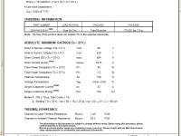
PLEAE REFER TO THE PDF FILE FOUND HERE FOR SPECS http://www.necel.com/nesdis/image/D18760EJ2V0DS00.pdf

HERE IS A VIDEO TEST RIDE WITH ME FOLLOWING ... Video Done around 1am so its dark ....


http://www.youtube.com/watch?v=7xSF97LL1SU


P.s. Please ask any questions in regards to the controller and i will update this post according with answers to give you as much info as possible for this controller!; All you feedback will be appreciated


thank you!
-steveo
 
fechter said:
Cool.

How does the timing advance and "gear" thing work?

It's amazing how similar these different chinese controller look on the inside. I like the heat sinks on the voltage regulators (hope they're glued or screwed to the board).

It should be relatively easy to mod it for higher voltage.

The gears switch by putting a push switch to change it into different modes on the "gear selection option"

The timing mode in the high option in mode 3 kicks in at a certain rpm.

It changes the timing .. the best way i could explain it is the hall sensors as you know go in a specific order .. but in high mode instead of going example blue hall ;green hall; yellow hall it will basically go blue hall; Green/yellow hall at same time to advance the timming.


On thing i forgot to mention is the controller will switch into mode one when it detects you batteries are almost dry!


The heat sinks on the voltage regulators are screwed into the sink and pasted from factory.

-Steveo
 
will this controller work with most brushless motors?
those are heavy gauge phase wires...
is this 3 speed setup only for scooters or can it be used on a ebike?
 
wasp said:
will this controller work with most brushless motors?
those are heavy gauge phase wires...
is this 3 speed setup only for scooters or can it be used on a ebike?

I think the wires are silicone 12 or 14 awg wires

This controller can be used on scooters or ebikes with either 60 degress or 120 degree brushless motors

I will be placing powerpoles on one and putting it on my crystalite for you guys shortly to get the wiring straightend out!

-steveo
 
fechter said:
Can you read the numbers off the FETs and the microcontroller chip?

Hey Fechter

Mosfets read: NEC
k4145
77ks

datasheet
http://www.necel.com/nesdis/image/D18760EJ2V0DS00.pdf

can they take 100v? We ran 75v through them fine!

Micro controller Chip reads:

H5 GS168
0726V BG076Q1


-Steveo
 
steveo said:
wasp said:
will this controller work with most brushless motors?
those are heavy gauge phase wires...
is this 3 speed setup only for scooters or can it be used on a ebike?

I think the wires are silicone 12 or 14 awg wires

This controller can be used on scooters or ebikes with either 60 degress or 120 degree brushless motors

I will be placing powerpoles on one and putting it on my crystalite for you guys shortly to get the wiring straightend out!

-steveo
steveo the controller is a "120 degree controller" so it will work with a xlite motor the the timeing jumper is only for the advance or the hulls to trigger faster to that it free spins more and spins faster on the back side of the controller tho there is somthing that lables 120 and 60 on it but i still got to find out how it works with out killing thiss controller lol
 
steveo said:
can they take 100v? We ran 75v through them fine!

Hmm. I once built a peak power point tracker with 55 volt MOSFETS. Max panel voltage was around 65 volts. It worked - for about a week.
 
wrobinson0413 said:
I think that they will need the power fairy to come and put the magic smoke back in fets soon :lol:

billvon said:
steveo said:
can they take 100v? We ran 75v through them fine!

Hmm. I once built a peak power point tracker with 55 volt MOSFETS. Max panel voltage was around 65 volts. It worked - for about a week.

I don't think this is the case .. these mosfets are rated for 75v min or 100max; the controller is using name branded nec fets which is better then alot of other chinese controller i've ever opened.

******************************************************************

Does anyone know where i could find a better detailed pdf that would show resistance and voltage limit of these mosfets?

p.s. I will try to post photos or video of this controller on my 5304 26" hub motor on 66v of A123


thanks
-steveo
 
wrobinson0413 said:
Steveo,

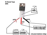
If you don't believe that you have the correct datasheet, one way to figure out what the maximum operating voltage of the device is to unsolder one mosfet, and tie the source to the gate. Then put a 1kohm resistor in series with the source/gate, and a ammeter in series with that. Set up you ammeter to read mA, and get an adjustable voltage supply and connect it across the Drain to the other side of the ammeter. Slowly adjust the voltage up until you read 1 mA. This will give you the maximum allowed voltage for the device at whatever room temperature you are at. Round that value down to the nearest number that is a multiple of 5 or 10, and you have your datasheet maximum voltage. If you are reading 106V then you have a 100V device, and if you are reading 64V the you have a 60V device, etc. Note, the numbers I put there are for illustration purposes only.

Hey

thanks for explaining this!; I will give it a try if i will be going higher then 66v!.. for now i think at 66v they will be fine.

I'm having a slightly different problem right now .. I can't get the hall wires & motor phase wires straightened out for the motor to run properly. My neighbor suggested making an led mini harness for the hall sensor wires to firgure out the firing order of the hall sensors. he uses this method when getting this controller and others to work on different wiring configuration between motor/controllers.

does any one have any alternative way of figuring it out?... Ive been trying the mixing and matching config .. but it feels like i may be here for hours.. even though its worked in the past :p

thanks
-steveo
 
steveo
tried to do a pic of your breakdown voltage test circuit for mosfet,
can you tell me is this correctbreakdown voltage test.jpg
 
i wonder would you have any suggestions for testing max amp of mosfets, reason being: the irf4110 mosfets from mexico are quite expensive, there are two different ones also made in china, but they are quite cheap, if its possible to do some fairly simple test to see if they will handle say 50amps for short time, they still might be useful if the bad ones can be weeded out before installed into controllers. Even better if can find what max amps they will go to without blowing them.
 
well guys i got some good news and bad lol the good news is i think the single speed version of thiss controller can be converted to a 3 speed the bad news is that steveo some how blew alll the mos fets on the 3 speed controller i gave him lmao he was useing my hall tester with a led display and a test circuit he gave it to much throttle in test mode lol so looks like i got some fixing to do so far we are out of fets so looks like it will be a bit b4 we post up what happend
 
thanks wrobinson for info on max amps, sounds tricky to test, the chinese made 4110 I've used at 86volt at 35amp with x5303 ( getting 79km/hr top speed), so they probably aren't too bad, the problem is some of the fets will fail on first use, seems if they are ok on first run they keep going, so weeding out bad ones they might not be too bad. Looks somewhat problematic to test them unfortunately.
 
Hey everyone

I had originally tried this controller in the past on my x5304 and could not get it to turn the motor smoothly .. it seems that no matter how many combinations i tried .. to get the motor to rotate properly .. it would feel like a really rought vibrating motor ...

A few months later .. today .. i re-visited this controller again .. myself not understanding why a 120 degree controller wouldn't work with a 120 degree motor .. my neighbor having played alot with these controllers at work told me that its possibly the hall sensors.. as per he had a similar problem with a particular motor at his work..

It turned out he was RIGHT!! .. I tried the same controller on my x405 motor .. that i had replace all hall sensors last year with new ones after they where damage from a spun shaft .. and the motor spun up perfectly on the first shot! .. The halls where provided to me from my friends work :)

All i know is my x5304 is an old gen x-lite .. maybe the reaction time is slower ..

I will be putting 4110's in one controller to test it at 100v before pushing this controller to 133v also .. and see if i will get the shutter or not that i was getting on my knockoff e-crazyman 133v controller

-steveo
 
Hey everyone

I finally installed somd fdp2532 fet in this controller; single speed version

I only used 6 mosfets to test...

upgraded the capasitors

.. here is a video of it running on my bike! very short test ..

I even have the Cycle analyst port on it and all options on it works perfectly!!

http://www.youtube.com/watch?v=rTEJ3ZYnZ6c

-steveo
 
Back
Top