2018 Torque Arm Tests, Splined Interface Design and Tabbed Washers

ZeroEm said:
He is on his second front 1500w leafmotor (run with less than 400w) one torque arm on alloy front forks.

Why such a big motor for only 400W? And what happened to the first one?
 
by Balmorhea » Aug 25 2020 12:04am

ZeroEm wrote: ↑Aug 24 2020 4:44pm
He is on his second front 1500w leafmotor (run with less than 400w) one torque arm on alloy front forks.
Why such a big motor for only 400W? And what happened to the first one?

The first one was stolen so he had none. I started out working on the one one he has now. I found out I could not ride very far sitting on a bicycle seat so I stopped on the first bike and built my trike. The first bike I was planning was going to be a AWD full suspension 29er. Dual leafmotors 52v but things have a way of changing and he was on foot. I bought him his first kit and help him put it together. That was my first then I build my mother's trike for her then built my trike. I had no plans for the front leafmotor and my brother is cheap 36v 13amp controller. He can not hurt the motor but he can up grade to more power but he would only tear up the bike and hurt himself.
 
Hi
I make a custom frame design to fit the GMAC Motor. Does someone has the perimeter that the 11 holes make on the actual torque arm? And how thick is the torque plate and the torque arm? (I'm waiting until the motor is available again but in the meantime i can check if a i can design a nice rear dropout....) :D
 
If it helps, there's a cad model of the motor as a PDF on the product page:
https://ebikes.ca/product-info/grin-kits/gmac.html
down under the User Manual heading.
 
amberwolf said:
If it helps, there's a cad model of the motor as a PDF on the product page:
https://ebikes.ca/product-info/grin-kits/gmac.html
down under the User Manual heading.
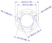
As it is a vector PDF, it is not too difficult to import into CAD. However most of the curves are a bunch a small straight line segments so converting those back into circles and radius's is not without some room for error. Here is my "best guess" for the Grin Gmac Torque Arm spline. Note: those holes for the TA bolts could be either M4 or M5 ... this drawing shows M4. The attached zip file has DXF and DWG files.
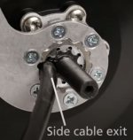
GMAC TA Closeup.jpg
GMAC Torque Arm Spline (Best Guess)850.jpg
 

Attachments

  • GMAC Torque Arm Spline (Best Guess).zip
    226.4 KB · Views: 7
I've built a GMAC rear wheel for a Benno Carry-On cargo bike and have run into an interference issue with the GMAC's splined torque arm (the design of which is discussed in this thread).

The Benno frame has a postmount brake tab which assumes that the locknut on the rear hub is 30mm or smaller in diameter. This is a safe assumption with almost all bike hubs, but the end of the GMAC that contacts the frame is 52mm in diameter. This is preventing wheel installation.

I'm wondering if anyone has designed a more compact torque arm for these hubs? I've also emailed Grin directly asking this question.

One design would be to copy what Grin sells, but to go from 6 fixing bolts to 2 fixing bolts located at the bottom (on either side of the cable). This would allow the major diameter of the torque arm around the axle to be reduced to 30mm for the tops and sides where the brake mount is located. I have access to a CNC mill so cutting parts for this is no problem, but I don't have access to a proper testing fixture like what Justin built in this thread.

The simplest thing to do is for me to file off the portion of the outer torque arm where it interferes with the brake mount. I don't need to file the splined disk, it doesn't interfere. This would change the outer circle of the torque arm so that it doesn't fully capture the inner -- which I think is okay but might not be.

This first photo shows the brake mount. On the second I used sharpie to mark what I would need to file away (only on the outer part of the torque arm).

1722297173254.jpeg

1722297236934.jpeg
 
I don't know why you'd use a GMAC unless you want regen braking. In that case, you amputate the goofy post mount nonsense and use regen braking on the rear wheel.

If that sounds hokey to you, well that's how I feel about using regen instead of real brakes. But I don't use them and I wouldn't use a geared hub without a freewheeling clutch.
 
This bike has a specific mission that does benefit from regen braking. I see regen as being like a drag brake on a tandem though, not a replacement for real brakes.

The bike is being built to carry trail maintenance gear up MTB trails for clearing trails in NE Washington. Based on my own experiences with a variety of hubs and the Grin hub and trip simulators the GMAC looked like the best option. The regen / drag brake effect will be handy on the way back down. Average ride is short, has lots of stops, and steep (approximately 1000' climbing in 2 miles).

Anyway, the wheel is already built and one way or another we'll use it.

Alex (who may have met you once at Bikesmith)
 
Last edited:
The simplest thing to do is for me to file off the portion of the outer torque arm where it interferes with the brake mount. I don't need to file the splined disk, it doesn't interfere. This would change the outer circle of the torque arm so that it doesn't fully capture the inner -- which I think is okay but might not be.

This first photo shows the brake mount. On the second I used sharpie to mark what I would need to file away (only on the outer part of the torque arm).

If you mean the lighter colored area on the arm mounting disc, I'm not sure if it will still do the job it needs to with that area missing. I also don't know if the arm itself can do it's job if missing that much area. Grin could probably answer that, if you can get a reply.


The pics don't show the whole frame back there so I can't see how the wheel would mount up, how all the parts would be relative to the frame, etc. But based on the apparent nut-marks on the dropout face, it looks like that's the outside face of the left side.

If so, then unless that post mount also extends to the inner face of the dropout, you don't need to do the modification you're looking at doing because that disc and the torque arm goes on the inboard side, not the outboard side.

If the inboard dropout face is flat, then it should all fit fine.

If that *is* the inboard dropout face, then you'd have to modify either the arm and/or disc, or the frame itself.

Does your application *require* a rear mechanical brake? Most (sometimes all) braking in most applications is done by the front brake, so you can probably get by without the caliper mount if necessary. However, you probably don't have to remove it, just remove enough of the interfering area to allow the torque arm to correctly fit, and that will probably not compromise the mechanical braking strength enough to cause any failures, especially if you are using the GMAC regen primarily.


Something to note about the GMAC, though, if noise is an issue, is that the smaller the wheel it is in, the louder it will be for any given speed. At 20MPH in a 20" wheel, it is very loud, especially under load (traction or braking). That is the main reason I ended up not continuing to use it on my SB Cruiser trike. (the secondary reason was that the Phaserunner would nearly always stop operating whenever I would hit bumps that allowed the wheel to "grab air" and spin faster then be jerked back down to road speed on landing, and I'd have to stop and power cycle or reset it. this doesn't happen using it on a DD hubmotor, just on the GMAC...but there are bumps like that in several high-traffic segments of my commute and it was too dangerous to lose power there).
 
The photo is the inboard side of the left dropout. The bike's stock rear hub was a Shimano Deore, which has steel locknuts that will leave an impression on an aluminum frame.

The rear disk caliper is needed since this will be used on MTB trails. The regen feature is being used as a drag brake, but not a stopping brake. The rear post of the mount will be floating in space if I remove the necessary material from the frame.

Thanks for the warning about noise. This bike has 24" wheels and noise is not a major concern. The bump issue that you brought up is much more concerning though since this will be used on bumpy trails.

The All-Axle isn't an option, I've built the same bike with one and it doesn't have the necessary low speed torque. A 20" wheel All-Axle (barely) does, but built into a 24" wheel the All-Axle is kind of gutless at the 5-8mph speeds that this bike will be ridden at.
 
Last edited:
The GMAC has some pretty good torque if you feed it enough current (but it will heat up if you feed it too much at too low a speed, just like any motor). There's two winds, so pick the one appropriate to your usage to help with that.

You can look at my SB Cruiser thread to see how it performed there, under most likely much higher loading than you'll be putting it thru (albeit in a significantly smaller wheel). The simulator at ebikes.ca can also show you how much torque you'll get if you need numbers.


This might help decide if it will be a problem or not:

The bump issue happens with the PR / GMAC combo because (I think) it's a torque-controller, not speed controller, so:

--the throttle input controls how much motor current is provided, not how much voltage (speed).

--unloaded, off ground, a motor takes very little current to be pushed rapidly to high speed

--the PR is a fairly advanced controller, and has a number of protections in place which include overspeed and overcurrent, and both of those probably also have error detection in place that the user cant' see or control that monitor how quickly either of those changes.

--So when the motor wheel comes off the ground while still being commanded to have sufficient current to push the bike under some reasonable load, it spins up VERY quickly to a much higher speed. Even if there is a speed limit in the PR it will take time for it to cease powering the motor and more time for the motor to spin down--either or both of these may exceed whatever controller limits there are for how fast it spins up and/or how long it is allowed to keep spinning fast before an error occurs, turning off the controller.

--when the wheel lands on the ground again the speed very suddenly drops back to whatever the road speed of the bike is, causing the reverse of the above.

--if the motor was stil being driven by the controller (didn't shutodwn from overspeed) then it will spike the phase currents in that moment as the load so suddenly changes from near zero to full, and the controller's current limits may engage or if it has protections against the spike itself it may shutdown to prevent damage from a potential phase short (which would be the normal cause for such spikes).

If you're using a dumb controller that just does speed/voltage control, not torque/current control, it would probably never have a problem (but it also cant' as effectively use the motor, and most of thsoe don't have variable regen braking, which you'd need to use the GMAC as a controllable rear brake vs just full-power on/off.


Note that using a motor as a drag brake is going to heat it, the controller, and the wiring up.

You'll have to test the system under actual conditions to find out whether it's a problem you have to fix or not.

How much it heats up depends on the braking it has to do and the environmental conditions, but it is usually faster heating than using it as a motor. A geared hub like the GMAC has two airgaps for heat to pass thru before it can exit the motor, so it heats up faster and stays hotter longer, making it often a less useful choice for this kind of thing in many applications than a big DD hubmotor. You might be able to add liquid coolilng to it if you find there's a heat problem; there are threads about that around here including one started by Justin_LE.

The controller, depending on it's design, has a number of easy ways to add heatsinking or active cooling (fans, etc) to prevent overheating it, and wiring can be cooled by removing the outer cable jacket and spreading the wires apart from each other so air will flow past each wire and heat isn't trapped inside the cable jacket / wire bundle.
 
I 'think that you may have skipped over my design brief, this isn't a standard e-bike. It is a bike for trail repairs and will be ridden straight up a hill (~2000 feet of climbing in about 3-4 miles) with lots of stops at ~8 mph (faster isn't an option with the trail site lines). On a green mountain bike climbing trail, carrying a chainsaw and other trail clearing eqiupment. Flat for a couple of miles. Turn around and go back down. The bike has a 24" wheel, so we're talking wheel speeds of about 60-80 rpm -- too slow for the direct drive hubs that I'm aware of. I already mentioned that I've modeled tons of hubs on Grin's calculators (both trip and motor simulator) and the GMAC is the best option that I've found. I do know about how the GMAC handles heat and think that we'll be okay because of the many stops.

The issue here isn't hub selection -- that is already decided and the wheel is built. I'm looking for feedback on how GMAC installations have dealt with frames that have features that interfere with the huge torque arm. I'm using a Baserunner, I don't think our application requires the higher current of the Phaserunner. It's likely that I'll lower the peak torque even on the Phaserunner.

I will add that this isn't a throttled bike, it will be ridden using proportional torque assist by a strong rider.
 
Last edited:
I have a proposed solution that I think will work without compromising strength too much. I'm going to mill off of the interfering part of the outer torque arm, but leave the ring intact that fully wraps the inner splined adapter. I may have to file about 2mm of the brake mount off to make space for the ring, but I'm comfortable with that minor modification to the frame.
 
Outside thoughts are appreciated. It just sounded like you hadn't read the usage case and so the thoughts weren't compatible with what the bike needed to do.

To close the loop I had a good thread with Justin on this. He says that they have run into this issue with other postmount frames, so it's not a unique issue for me. Hopefully there are updates to the GMAC info on the website. He also agrees that the GMAC is a good choice for this use case. One sharable useful tidbit is that the trip simulator does a better job than the motor simulator at modeling thermals, which is helpful to know since I'm pushing the limits there.

Before hearing back from Justin I modified the torque arm by machining a small window where two of the fixing bolts are that allowed space for the frame's brake mount. Justin says this will fail at full torque and he's probably right, because I removed a lot of material behind the inner splines of the outer torque arm. I'm going to scale down the peak phase amps on the Baserunner, which shouldn't be a problem for our use case. I'm also making a spare torque arm since they are pretty easy to machine.

His suggestion is to put a spacer between the axle and the dropout. I'm going to see how well that squeezes in, this is a very stiff frame with a stiff rack bolted to it, so spreading it isn't easy.

The first photo shows a prototype that I used to test the fit, the constrasting orange makes it easy to see how the window works.
1722549424841.png
The second photo shows the part after machining:
1722549479229.png

And the almost complete bike, as I've been testing it. The blue thing on the downtube is a CNC'd battery mount that I made initially, but then I figured out a way to fit the battery into the rear triangle. The tires will be growing in size to 24x2.6. Otherwise it's almost done and ready for it's trail repair missions.
1722549580027.png
 
@martinev That's interesting. I ended up making a completely new torque arm out of 6061 because that is what Grin uses. They've had these hubs in service for quite a while now and places like UW Mailing Services push them hard, so I feel like issues would have already shown up if 6061 was an issue.

I also detuned the Baserunner from 80A phase current down to 55A since this bike's application doesn't require maximum torque (off the line acceleration doesn't really matter at all). The new one that I made has solid webbing (instead of an open window) between the two areas, the bolt holes are rotated 30 degrees which allowed me to use 5 of the 6 bolts, and there is no hole where the 6th bolt would have gone.

I could easily make one out of steel, but don't want to damage the center portion which is 7075 aluminum. I think that the failure mode here is pretty minimal, the torque arm could only rotate slightly before jamming on the caliper mount and then the bike can be ridden back unassisted.

The second photo shows the modified original, a prototype that had some issues, and the back of the final one.

1723232987737.png1723233086924.jpeg
 
Back
Top