24 Mosfet Controller XJC8b116 microchip Information Thread

wshi said:
Hello steveo,

I am just wondering did you ever do a extreme condition test for the controller? As far as I know most major e-bike manufactures require their controller to pass stall start test, which is a test they deliberately welding a BLDC on the testing base so it can’t spin, then connect the controller and turn thrust to max, the controller should withhold 8~10 seconds over circuit without smoke or blow up. The test is usually repeated 3 times with 5 minutes gap. I heard last week while one of other potential supplier doing stall test with their 24-fets controller caught fire and their lab is almost destroyed. I am not kidding just be careful, high voltage plus huge current are powerful.

The Infineon does not stall. After a few moments it cuts power - so it will pass.

-methods
 
methods said:
wshi said:
Hello steveo,

I am just wondering did you ever do a extreme condition test for the controller? As far as I know most major e-bike manufactures require their controller to pass stall start test, which is a test they deliberately welding a BLDC on the testing base so it can’t spin, then connect the controller and turn thrust to max, the controller should withhold 8~10 seconds over circuit without smoke or blow up. The test is usually repeated 3 times with 5 minutes gap. I heard last week while one of other potential supplier doing stall test with their 24-fets controller caught fire and their lab is almost destroyed. I am not kidding just be careful, high voltage plus huge current are powerful.

The Infineon does not stall. After a few moments it cuts power - so it will pass.

-methods

thats one way to pass the test LOL..

-steveo
 
Steveo - I think you missed my point.

What I am telling you is that R10 / R11 / R12 is a voltage divider that feeds a ratio of the full system voltage right into the microcontroller.
This voltage divider has been tuned to make sure that the maximum physical input voltage of the microcontroller A-D is not overcome.
This is probably like 5V or something similar.
If you increase the system battery voltage then you must calculate the final voltage that will appear at the A-D input of the microcontroller and readjust that ratio to ensure that you do not overstress the microcontroller input.

If you drive the input too high (or above spec) you can blow out the internal A/D which will result in the microcontroller thinking the system voltage is out of band which will cause it to lock up.

Performance - i.e. regen & LVC are secondary to the electrical requirements and characteristics.

You are going to need to decrease R12 by a fixed amount in addition to the pot in parallel. Most likely by adding an additional guard resistor in parallel to ensure that the max voltage is not overcome. The calculations are trivial - you just need to measure those components. Knuckles can help you with the calculation.

-methods


steveo said:
Hey Methods,

I did confirm the adjustable pot goes in parrallel with the r12 resistor to adjust the lvc as per keywin. I have a feeling the LVC in the software isn't anywhere over the 100v mark, probably similar to the 18 mosfet software, I've request the software from keywin, and asked about that LVC pot issue, I haven't installed it at this time, worst case scenario, I could get a modded cycle analyst to cutout the battery, I really would like the big display version :D

-steveo
 
methods said:
Steveo - I think you missed my point.

What I am telling you is that R10 / R11 / R12 is a voltage divider that feeds a ratio of the full system voltage right into the microcontroller.
This voltage divider has been tuned to make sure that the maximum physical input voltage of the microcontroller A-D is not overcome.
This is probably like 5V or something similar.
If you increase the system battery voltage then you must calculate the final voltage that will appear at the A-D input of the microcontroller and readjust that ratio to ensure that you do not overstress the microcontroller input.

If you drive the input too high (or above spec) you can blow out the internal A/D which will result in the microcontroller thinking the system voltage is out of band which will cause it to lock up.

Performance - i.e. regen & LVC are secondary to the electrical requirements and characteristics.

You are going to need to decrease R12 by a fixed amount in addition to the pot in parallel. Most likely by adding an additional guard resistor in parallel to ensure that the max voltage is not overcome. The calculations are trivial - you just need to measure those components. Knuckles can help you with the calculation.

-methods


steveo said:
Hey Methods,

I did confirm the adjustable pot goes in parrallel with the r12 resistor to adjust the lvc as per keywin. I have a feeling the LVC in the software isn't anywhere over the 100v mark, probably similar to the 18 mosfet software, I've request the software from keywin, and asked about that LVC pot issue, I haven't installed it at this time, worst case scenario, I could get a modded cycle analyst to cutout the battery, I really would like the big display version :D

-steveo

Hey methods,

thanks for clarifying, sorry i'm not to familiar with how everything works on this controller board, but i'm doing my best to understand. I will post the values of all resistors:

R10 / R11 / R12


-steveo
 
Steveo,

Nice job on the bus soldering (I think you missed a spot - Ha Ha ... Only kidding).

I've traced the R12 circuit on the new 24-fet board ... it can be modded. BUT I have a better way.

No need to mod anything. Just make sure that the Vcc never exceeds say 90 volts.
My idea is simply to use a zener BETWEEN the red ignition wire and the Vcc.
It all depends on your desired "voltage window" and also if you want high voltage regen.

The max regen value (software) is still a too low at 75 volts even in the latest flash application.

Example:
Let's assume we have 10 SLA bats in series (10x12v=120v nominal).
LVC should be 10x10v=100v and HVC(max regen) should be 10x14v=140v.
So our example voltage wondow is 100v to 140v.

So we can trick the Vcc circuits by adding 140v-75v=65v zener(s) between the ignition wire and Vcc.
No need for that power resistor either ... just use a small length of wire.

So real regen will be 75v + 65v (zener) = 140v
Program the LVC to be 35v
So real LVC will be 35v + 65v (zener) = 100v

You can use two 5W zeners in series to make up the 65v value.
The max current thru the zeners is NEVER more than maybe 40ma at the high voltages.
So ... 65 V x .04 A = 2.5 Watts. This is not so bad at all as an easy fix.

We can play around with zener idea too (many other options).
All depends on how you want to "trick" the controller and make it do exactly want you want.

-K
 
Knuckles said:
Steveo,

Nice job on the bus soldering (I think you missed a spot - Ha Ha ... Only kidding).

I've traced the R12 circuit on the new 24-fet board ... it can be modded. BUT I have a better way.

No need to mod anything. Just make sure that the Vcc never exceeds say 90 volts.
My idea is simply to use a zener BETWEEN the red ignition wire and the Vcc.
It all depends on your desired "voltage window" and also if you want high voltage regen.

That does not make any sense. You would never be able to set LVC to a useful voltage and you would never be able to limit the top regen voltage.
Why would you make it non-linear by clamping with a diode (which is modding by the way) when you could just correct the voltage divider and have a useful LVC and Regen range?
The resistor mod is cheaper, more reliable, more efficient, and results in full functionality.

If you could just string Zener diodes in series to shrug off the voltage then dont you think that is what they would have done already?
You are talking about dropping 50V @ 70mA - that is 2.5W.... 2.5W
Think it through.

I am not going to do this thing again where I try to help and you talk past me Knuckles.
I believe this is how we started off in your "Infineon for retards" thread.
Good luck to you sir - I want no part of working with you :p

-methods
 
Hey Everyone,

Could anyone tell me what is the max current draw i could pull out of my 24 mosfet irfb4115 controller? is there a way to calculate it? all i know is that 104amps is the max draw of each mosfet if i'm not mistaken...

the data sheet also indicade that at 100 degress max draw is 74 amps, and at 25 degress 104 amps max!

now .. if we just do a quick comparison .. a irfb4110 with do 180amps @ 25 degress & at 100 degress it will do 130amps continous!! ..

good thing there is 24 mosfets in this controller :D

also,

is there a resistor i could place on the shunt, (just like methods did) to adjust the max current draw of the controller? a link to the part would be awsome ..

thanks
-steveo
 
Steveo,

Looks like you have a 200 ohm resistor installed on the controller.
http://i48.tinypic.com/s4ouax.jpg
If you apply more than 110 volts to Vcc you will probably fry the 100 volt schottky diode (D8).
(as well as blow the cap - C2)

-K
 
Knuckles said:
Steveo,

Looks like you have a 200 ohm resistor installed on the controller.
http://i48.tinypic.com/s4ouax.jpg
If you apply more than 110 volts to Vcc you will probably fry the 100 volt schottky diode (D8).
(as well as blow the cap - C2)

-K

Hey knuckles,

I'm actually running a 200ohm & 330ohm resistor in series to accomidate the higher voltage!

heres a few photos i posted a while back

14doahz.jpg

262v8xz.jpg


video

http://www.youtube.com/watch?v=pjX1e3NiWvo

-steveo
 
What voltage did you no-load test (143 volt from vid)?
What is the current draw on the red ignition wire?
(you can use a 10 ohm resistor in line with the ignition wire and measure the voltage drop across the 10 ohm resistor)

The current thru the ignition wire will tell you the voltage drop across the 530 ohm (4W) power resistor.
And also the calculated heat dissipation of the 530 ohm (4W) power resistor.
 
steveo said:
Hey Everyone,

Could anyone tell me what is the max current draw i could pull out of my 24 mosfet irfb4115 controller? is there a way to calculate it? all i know is that 104amps is the max draw of each mosfet if i'm not mistaken...

the data sheet also indicade that at 100 degress max draw is 74 amps, and at 25 degress 104 amps max!

now .. if we just do a quick comparison .. a irfb4110 with do 180amps @ 25 degress & at 100 degress it will do 130amps continous!! ..

good thing there is 24 mosfets in this controller :D

also,

is there a resistor i could place on the shunt, (just like methods did) to adjust the max current draw of the controller? a link to the part would be awsome ..

thanks
-steveo

Few month ago I did some boundary test on our 72V 24FET IRFB4110 controller with EC dynamometer....
Here is one successful record

Oct. 3 2009
Room Temp. (begin/end) 31C/88F / 39C/102F
Controller Case Temp. 85C/185F (torque is a function of temperature)
Continuous Current Draw (begin/end): 300A/99A
Holding Time: 120 Minutes
Hub Motor: 72V 6000W 16'' 1600RPM
 
Knuckles said:
What voltage did you no-load test (143 volt from vid)?
What is the current draw on the red ignition wire?
(you can use a 10 ohm resistor in line with the ignition wire and measure the voltage drop across the 10 ohm resistor)

The current thru the ignition wire will tell you the voltage drop across the 530 ohm (4W) power resistor.
And also the calculated heat dissipation of the 530 ohm (4W) power resistor.

Hey knuckles,

I have to check the current, but i did do a temp reading on the resistors and is was about 56 degress on idle!

-steveo
 
The reason I mention the "ignition" wire current is because the buck converter circuit
should draw LESS current at higher voltages and MORE current at lower voltages.
If you are drawing a high "ignition" wire current (say 80ma) at 140v then something may be seriously bad.

You can check the "ignition" wire current at Vcc = 140v, 120v, 100v and 80v.
You may be surprised at the results. Better safe than sorry.
 
Knuckles said:
What voltage did you no-load test (143 volt from vid)?
What is the current draw on the red ignition wire?
(you can use a 10 ohm resistor in line with the ignition wire and measure the voltage drop across the 10 ohm resistor)

The current thru the ignition wire will tell you the voltage drop across the 530 ohm (4W) power resistor.
And also the calculated heat dissipation of the 530 ohm (4W) power resistor.

Hey Knuckles,

could you better explain how to do this? a quick diagram would help me understand...

or i could use a multimeter? ... mine won't display below .01amps

-steveo
 
Hey Knuckles,
could you better explain how to do this? a quick diagram would help me understand...
or i could use a multimeter? ... mine won't display below .01amps

Steveo,

First off I really like your controller wiring scheme.
1) Main capacitor pre-charge (momentary) push switch.
2) Main battery power supply (breaker?) switch.
3) Controller on-off (button) “ignition” switch.

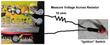
The current thru the controller on-off button “ignition” switch is what I think you should measure.
This is what powers the controllers “brains” and should be well under 100ma.
Steveo_Ignition_on-off_switch.jpg
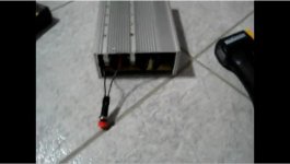
I assume your on-off button switch will be mounted on the end plate of the controller.
Me … I like to run these same wires to a key switch on my handlebars. Same concept as you but I like key switches
(and my “ignition” wire leads are long and easy to splice into for measuring current).

You’ve done such a nice job wiring that I don’t want you to cut any wires.

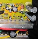
If possible, just unsolder the lead wire that goes to the “ignition” Vcc (next to your double power resistor)
then use a temporary length (say 8”) of wire and solder that to Vcc.

Steveo_Ignition_on-off_wires.jpg
Then just quickie solder a 10 ohm (1/2 watt) resistor in-line between the button switch wire and the temp 8” wire.
It’s only temporary and just for testing the ignition current.

Your multimeter can easily measure milli-volts.
So just measure the (milli-volt) voltage drop across the in-line 10 ohm resistor.

Examples of what you may observe with the 10 ohm resister (in-line) with your switch…

I = V / R

You might measure 500 milli-volts (0.5 volts) across the 10 ohm resistor.
So now you know the current is 0.5 / 10 = 50 milli-amps.

You might measure 800 milli-volts (0.8 volts) across the 10 ohm resistor.
So now you know the current is 0.8 / 10 = 80 milli-amps.

etc.
 

now thats the diagram i was talkin about :D

-steveo
 
(Revised 10-17-2010 for technical corrections)

Steveo,
I have confirmation from Keywin about the components on the 24-fet controller.
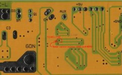
Refer to the “Buck” circuit … Picture of board here ...

file.php


1) Capacitor C2 is 160v (you may wish to confirm this).
2) Shottky diode D8 (SS110) is 100v.

Basically this means it may be possible to damage the D8 shottky diode
if the voltage at cap C2 is greater than 100v.

otoh ...
3) Keywin said Vcc=150v will not “hurt” the R12 (LVC-HVC) circuit or the “116” chip.
This may be correct. if you don’t care about high voltage regen then you can leave the R12 circuit alone for now.
Easy enough to mod R12 (lower the R12 ohm value) when the time comes.

I did ask Keywin about the “ignition” circuit current draw. He didn’t test it at different voltages but remembers about 42ma (maybe at 72V).
YOU should still do this test yourself. The current is LESS as the voltage is HIGHER).

262v8xz.jpg
 
Knuckles said:
(Revised 10-17-2010 for technical corrections)

Steveo,
I have confirmation from Keywin about the components on the 24-fet controller.
Refer to the “Buck” circuit … Picture of board here ...

file.php


1) Capacitor C2 is 160v (you may wish to confirm this).
2) Shottky diode D8 (SS110) is 100v.

Basically this means it may be possible to damage the D8 shottky diode
if the voltage at cap C2 is greater than 100v.

otoh ...
3) Keywin said Vcc=150v will not “hurt” the R12 (LVC-HVC) circuit or the “116” chip.
This may be correct. if you don’t care about high voltage regen then you can leave the R12 circuit alone for now.
Easy enough to mod R12 (lower the R12 ohm value) when the time comes.

I did ask Keywin about the “ignition” circuit current draw. He didn’t test it at different voltages but remembers about 42ma (maybe at 72V).
YOU should still do this test yourself. The current is LESS as the voltage is HIGHER).

262v8xz.jpg

Hey Keywin,

Is it safe to add the resistor on r12 to adjust my LVC now? Regen is not of interest to me unless i'm planning to detroy my dropouts!! lol..


thanks
-steveo
 
Programmable LVC and Regen (HVC) values …
http://98.131.176.65/endless-sphere/V090914-214-100A.exe
LVC - 18.8v thru 65.5v with plenty of values in between. Take your pick.
HVC - 55v, 60v and 75v values.

R12 (as shipped) = 1200 ohm

Example 1: Solder a 1000 ohm (1/2 watt) resistor.
“New” R12 now becomes 1 / [(1/1200) + (1/1000)] = 545 ohm
So a LVC “program” value of say 60v is now actually (60v) x (1200/545) = 132v
And a Regen (HVC) “program” value of say 75v is now actually (75v) x (1200/545) = 165v

Example 2: Solder a 2000 ohm (1/2 watt) resistor.
“New” R12 now becomes 1 / [(1/1200) + (1/2000)] = 750 ohm
So a LVC “program” value of say 60v is now actually (60v) x (1200/750) = 96v
And a Regen (HVC) “program” value of say 75v is now actually (75v) x (1200/750) = 120v

Bottom line ... Choose a resistor value that suits your needs based on the available LVC and HVC program values.

Solder the resistor either from the top or the bottom (which ever is easier).

R12-1.jpg

R12-2.jpg
bada fuckin bing :roll:
 
Hey Everyone,

I will be adding a list of interested buyers of the new 24 mosfet kit to the first post, if anyone is interested please pm me directly and i will add you there. I will be offering the kits fully built or diy assemble it yourself kits!!!!!!

thanks
-steveo
 
GreenKnight said:
Yo Steveo

Can you provide a website or info source describing this microchip (doesn't google well) and a circuit schematic of the board.

Ta muchly in advance

calling on knuckles, he is your guy on this..

-steveo
 
GreenKnight said:
Yo Steveo
Can you provide a website or info source describing this microchip (doesn't google well) and a circuit schematic of the board.
Ta muchly in advance
There really is no website that has all the info you seek.
ES really is the place to get info on the XieChang controllers.
The Chinese really do not cater to our North American market.

But we on ES do understand these controllers very well and the XieChang "brand"
is pretty much "main stream" at this point. Our main contact for these products is Keywin in Hong Kong.
ecrazyman@gmail.com
 
GreenKnight said:
Yo Steveo

Can you provide a website or info source describing this microchip (doesn't google well) and a circuit schematic of the board.

Ta muchly in advance

The 116 is a custom chip made for Xie-Chang.
https://endless-sphere.com/forums/viewtopic.php?f=2&t=12416

All of the Xie-Chang 116 based controllers are similar, except the number of paralleled FETs and the input power supply. There is a schematic here:
https://endless-sphere.com/forums/viewtopic.php?f=2&t=12616#p187904
 
Back
Top