Hey Knuckles,
could you better explain how to do this? a quick diagram would help me understand...
or i could use a multimeter? ... mine won't display below .01amps
Steveo,
First off I really like your controller wiring scheme.
1) Main capacitor pre-charge (momentary) push switch.
2) Main battery power supply (breaker?) switch.
3) Controller on-off (button) “ignition†switch.
The current thru the controller on-off button “ignition†switch is what I think you should measure.
This is what powers the controllers “brains†and should be well under 100ma.

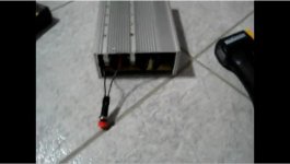
I assume your on-off button switch will be mounted on the end plate of the controller.
Me … I like to run these same wires to a key switch on my handlebars. Same concept as you but I like key switches
(and my “ignition†wire leads are long and easy to splice into for measuring current).
You’ve done such a nice job wiring that I don’t want you to cut any wires.
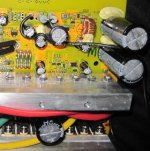
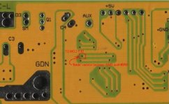
If possible, just unsolder the lead wire that goes to the “ignition†Vcc (next to your double power resistor)
then use a temporary length (say 8â€Â) of wire and solder that to Vcc.

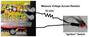
Then just quickie solder a 10 ohm (1/2 watt) resistor in-line between the button switch wire and the temp 8†wire.
It’s only temporary and just for testing the ignition current.
Your multimeter can easily measure milli-volts.
So just measure the (milli-volt) voltage drop across the in-line 10 ohm resistor.
Examples of what you may observe with the 10 ohm resister (in-line) with your switch…
I = V / R
You might measure 500 milli-volts (0.5 volts) across the 10 ohm resistor.
So now you know the current is 0.5 / 10 = 50 milli-amps.
You might measure 800 milli-volts (0.8 volts) across the 10 ohm resistor.
So now you know the current is 0.8 / 10 = 80 milli-amps.
etc.


