26650 Voltage drop under load

Cuprani

100 mW
Joined
Jan 14, 2019
Messages
39
I recently bought a custom build vector with a broken Ali Express battery.

It's a 72V 20S4P 26650 pack, so the battery contains 80 pieces of 26650 cells.
The cells have no text on them at all, so I don't have any specs.
Probably the cheapest cells available.

The problem with my 6kW bike is that the voltage dropped below 60V with only 25% throttle.
I could ride the bike when fully charged, but only if I were very gentile on the throttle. After a while I couldn't even look at the throttle without the controller limping into safe mode and shut down the bike.

In order to fix the problem I dismantled the battery. I've measured an average voltage of every pack of about 3,6V, but found 1 pack that only had 2,8V.
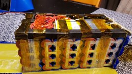
VT_BatteryTest(4).jpg

I extracted it from the battery, and when I did a full recovery cycle for those four cells, one cell was only able to store 200 mah while the other 3 were around 3500 mah.
View attachment 4

I've tested the 4 cells of the broken pack separately under load in order to have something to compare to.
View attachment 2

And I've tested the first 11 series of the battery under load (I didn't want to dismantle the other half of the battery for now, only tested half of the battery)
View attachment 1

Here are the results

(*The battery pack wasn't fully charged, but the separate battery's were)

Questions
- Are these normal figures under these kind of loads?
- Is there anyone that can explain why my voltage is higher under 10A of load then under 5A of load?
- Is it better to replace one cell, and combine it with the other 3 to make a new parallel pack? (this way the four battery's will level out and it won't have a huge affect when the internal resistance of the new cell is a little different. The cons are that the other 3 cells probably are damaged as well because the voltage of this pack was way lower then the rest.)
- Or is it better to place 4 new cells in this pack (with the chance that it has another internal resistance which will cause the BMS to have a hard time to balance the battery)

I know this battery pack will never give me top notch results, but I'll hope I can get it restored cheap while I'm still building and testing my bike.
 
Note: I've replied only to the text portion of your post, as I cannot see the images. If you attach them directly to your posts in the attachments tab, anyone that can see your post can see the images too.

Cuprani said:
It's a 72V 20S4P 26650 pack, so the battery contains 80 pieces of 26650 cells.

The problem with my 6kW bike is that the voltage dropped below 60V with only 25% throttle.

If the bike only draws 6kw maximum, then at an average of 72v that's 84A total. If 6kW is the average, then it's peak power demand may be MUCH higher, so you could have as much as double that current as a peak (since voltage sag will be worse the current has to increase even more to compensate).

For a 4p pack, that means at least 21A *per cell* (up to 42A :!: in the worse case!) which is pretty extreme for cylindrical cells (either 18650 or 26650) (even though spec sheets list a max current of 20-30A per cell for individual cells on certain 18650s, that's pushing them really hard and will have significant heating and voltage sag, and impact their lifespan negatively).

Even with high grade cells, I'd use a pack that is at least double that size, and for good performance at good lifespan I'd probably quadruple it.

You can get cells that can output a lot of current, but they don't hold as much capacity...so you get less range, and they tend to wear out faster too. And even those cells will sag more and output less current as the pack empties on any particular ride, for the same throttle demand.


one cell was only able to store 200 mah while the other 3 were around 3500 mah.
Then that's a dead cell, so you'd have to replace at least that one. But I would bet that even with it replaced, the pack is still going to have problems because it is too small to meet the power demands.


- Is there anyone that can explain why my voltage is higher under 10A of load then under 5A of load?
Sounds like a testing artifact. I'd look at the way the test was done to see if it's accurate--if it's really drawing only 5A at that point, using a separate current and voltmeter from whatever is being used to do the other measurements with (at the same time as the other stuff is also being used).


- Is it better to replace one cell, and combine it with the other 3 to make a new parallel pack? (this way the four battery's will level out and it won't have a huge affect when the internal resistance of the new cell is a little different. The cons are that the other 3 cells probably are damaged as well because the voltage of this pack was way lower then the rest.)
- Or is it better to place 4 new cells in this pack (with the chance that it has another internal resistance which will cause the BMS to have a hard time to balance the battery)
Whatever the reason for that group to be different in characteristics from the others, for either 4 new cells or 1 new and 3 possibly damaged, it'll still have the potential balance issues.

Since you don't know what cells they actually are, almost certainly any cells you get will be different from what you have in some characteristic(s).


You'd probably just have to always leave the charger on the battery until it is balanced. If there is no external indication of this, you'd have to just wait until the charger stops cycling on and off (which can take days or even weeks for severe imbalances, depending on the pack size, the imbalance amount, and the balancing current per channel of the BMS).

Or just leave it on the charger all the time you're not using it, to let it do whatever it can / needs between rides. If you do this I'd recommend having it in a non-dangerous location (to you or others) in case something *else* is wrong with the pack that you don't know about yet.
 
amberwolf said:
Note: I've replied only to the text portion of your post, as I cannot see the images. If you attach them directly to your posts in the attachments tab, anyone that can see your post can see the images too.

Thanks for your comprehensive answer.
I've uploaded the images to the site now, so you now should be able to see the test results.

If the bike only draws 6kw maximum, then at an average of 72v that's 84A total. If 6kW is the average, then it's peak power demand may be MUCH higher, so you could have as much as double that current as a peak (since voltage sag will be worse the current has to increase even more to compensate).

For a 4p pack, that means at least 21A *per cell* (up to 42A :!: in the worse case!) which is pretty extreme for cylindrical cells (either 18650 or 26650) (even though spec sheets list a max current of 20-30A per cell for individual cells on certain 18650s, that's pushing them really hard and will have significant heating and voltage sag, and impact their lifespan negatively).

Even with high grade cells, I'd use a pack that is at least double that size, and for good performance at good lifespan I'd probably quadruple it.

I'm currently running with an Ali Express controller (Leili) which is 72V 80A max. I don't know what spikes it will handle.
I bought a new controller which can handle 200A max (a custom build ESC), but that's for future purposes. If possible I would like to use this old battery to get the bike up and running with the new controller and do some testing.

Since you don't know what cells they actually are, almost certainly any cells you get will be different from what you have in some characteristic(s).

You'd probably just have to always leave the charger on the battery until it is balanced. If there is no external indication of this, you'd have to just wait until the charger stops cycling on and off (which can take days or even weeks for severe imbalances, depending on the pack size, the imbalance amount, and the balancing current per channel of the BMS).

Or just leave it on the charger all the time you're not using it, to let it do whatever it can / needs between rides. If you do this I'd recommend having it in a non-dangerous location (to you or others) in case something *else* is wrong with the pack that you don't know about yet.

I bought a new BMS as well. A smart BMS with Bluetooth. So maybe it would take forever to balance, but at least I can check the status. The old BMS was rated for 40A. My new smart BMS is rated for 100A continuously and peaks of 200A.
 
Cuprani said:
I've uploaded the images to the site now, so you now should be able to see the test results.
I'd guesstimate that the table of cell results is probably average to lowish for average cheap cells, but the test there is only pulling about 2.5A per cell at the highest load of 10A. That's not even a 1C load.

So the test does not push them even an eighth as hard as your bike does, assuming you're actually pulling the currents the controller is capable of. To get an idea of what's really happening to them you'd have to run the test at 80A. I expect you'd see a pretty serious sag on them, much worse than you do now. If you measured the temperature, you'd also see a quick and probably large heat problem.

One problem with the test is that the cells didn't start balanced, and some of them are well below the middle of the charge curve, and some are well above it, and some are around that area. So you can't even really compare one group's results to another, as their response to load will change with state of charge.

Without knowing the actual cell specs, like the discharge / load curves, from the manufacturer of the cell, and the conditions they tested them under, we can't know if these are correct results for these specific cells, however.


I'm currently running with an Ali Express controller (Leili) which is 72V 80A max. I don't know what spikes it will handle.
Most likely it'll be somewhat to well above that 80A for very short spikes (a few seconds), and then limit down to about that 80A once it reaches whatever time limit for "block time" (or whatever that manufacturer calls it) is programmed in to them at the factory. (some controllers are user-programmable; most are not).

FWIW, if it really is only 80A max, it is really only a 5760W controller at the 72v average voltage of a pack. It would be higher when a pack is completley fully charged, but that will also depend on voltage sag (the problem your pack is having) under that load.


I bought a new controller which can handle 200A max (a custom build ESC), but that's for future purposes.
That is probably going to need to be a pretty hefty battery if it's made of these kinds of cells. :/

You may want to look into cells more designed for high current use, like those for EVs (often prismatic or pouch type), so that you can get high currents and still have high capacities, and longer lifespan.


I bought a new BMS as well. A smart BMS with Bluetooth. So maybe it would take forever to balance, but at least I can check the status. The old BMS was rated for 40A. My new smart BMS is rated for 100A continuously and peaks of 200A.
Well, don't use the new BMS on the old pack. If you already are, you should swap it back, unless you can change the current limit of the BMS down to match the old max of 40A, and *verify* that it does not allow more than that to be pulled from it. It should also shut off the output once the limit is exceeded (perhaps after a very short delay rather than instantly).

The BMS is supposed to be used to protect the cells, (and to protect you from a fire) so that means ensuring it's current limit is *lower* than what the cells coudl actually do. If you use a BMS that allows more than double the pack design to be pulled from the cells, it is allowing the system to severely overload and potentially overheat the cells, and can allow a fire to happen.

Such a fire tends to be unexpected and people generally don't respond quickly (or correctly) to them; they can also happen when they aren't present and the fire can spread very very quickly to nearby structures (houses, etc); it's pretty intense and can be huge even for a small pack.

It may never happen. But if it does, it's disastrous. So I'd do whatever I could to prevent it. :)
 
If you were using the 80A controller with the 40A BMS, and the pack didn't just plain shut off when you slammed on throttle (regardless of charge level), then either the BMS isn't really shutting off like it should to protect against overcurrent, and is unsafe to use on the pack, or it's mislabelled, or the controller isn't actually pulling more than just 40A at worst case.

If the last is true, then several possible points come to mind, not all of which have to be the case at the same time:

--the cells are even worse off in condition than previously thought, since the current drawn is half (or less) of what was thought, but still has such a bad sag problem.

--the controller itself isn't really an 80A controller (either mislabelled, marketed with a lie, defective, or misprogrammed)

--the bike/system never sees a load high enough to force the controller to draw 80A.
 
On the table of results, the discrepancy between 5A and 10A is most likely the tester not actually reporting the correct current during the test.

Could be a display bug, or a problem in it's test method, or a flat out lie about what it's capable of, or a problem with the way the manual is written on how much current it can actually handle at a particular voltage, etc., or various other issues.

But it comes down to the tester not doing what you think it is.

You can verify this by using an ammeter (or multimeter on amps) between the tester and the cell (group) in question. If it's amps don't match the tester display, the tester is probably wrong--especially if it *does* match at some current levels but not at others.
 
amberwolf said:
The BMS is supposed to be used to protect the cells, (and to protect you from a fire) so that means ensuring it's current limit is *lower* than what the cells coudl actually do. If you use a BMS that allows more than double the pack design to be pulled from the cells, it is allowing the system to severely overload and potentially overheat the cells, and can allow a fire to happen.

I understand, but with my new controller I can control my maximum battery amps and maximum motor amps seperately. So I can limit the amps getting out (and into) the battery. So I will start with 20A and build up slowly.

With the new BMS I will have the benefit to constantly monitor the voltage of each parallel pack and know the actual status at all time. It also has 4 temperature sensors so I can monitor the heat build up as well. If I can somehow manage to output this signal to controller I can even protect my battery with my controller.

amberwolf said:
If you were using the 80A controller with the 40A BMS, and the pack didn't just plain shut off when you slammed on throttle (regardless of charge level), then either the BMS isn't really shutting off like it should to protect against overcurrent, and is unsafe to use on the pack, or it's mislabelled, or the controller isn't actually pulling more than just 40A at worst case.

It did shut off every time I hit throttle for more then 25%. I thought this was a protection from the controller and not the battery/BMS. As my old BMS doesn't have an on/off switch I don't see how this could be the BMS. But maybe I'm wrong.

Maybe the bike had never run properly. The seller told me it did, but I didn't trusted him. I didn't matter too me either because it was a bargain and I like to fix it myself.

Either way thanks for the information. For now I'll go for a quick and cheap fix and I will buy one cheap 26650 cell to rebuild the pack. I will use it with cair and I don't suspected to get good results with it. But for now it is a good alternative to rebuild the bike with the new controller. Mean while I will start saving some for a new battery build.
 
Cuprani said:
I understand, but with my new controller I can control my maximum battery amps and maximum motor amps seperately. So I can limit the amps getting out (and into) the battery. So I will start with 20A and build up slowly.
As long as there is something that lets you limit current, and *really* limit it, to a safe level for the cells, then you're "ok".

Keep in mind that many (most) controllers have some form of "block time" (could be called many things) that allows the controller to completely ignore it's current limit for a specified period of time, to help the motor get moving under load from a stop. Some controllers are programmable to let you change or even disable this, and some give you no access to this function. In that latter case, it will always peak higher (sometimes WAY higher) than the programmed current limit. Thankfully this is almost always a very short time (seconds at most...usually less). But it's still something to be aware of, and to check.


With the new BMS I will have the benefit to constantly monitor the voltage of each parallel pack and know the actual status at all time. It also has 4 temperature sensors so I can monitor the heat build up as well. If I can somehow manage to output this signal to controller I can even protect my battery with my controller.

If the BMS has temperature sensors, then it will, on it's own, act on those sensors. (if it doesn't have a way to do this, then having the sensors would be kinda pointless). You don't need to output the signal to the controller.

If the controller has temperature monitoring ability, you could use independent sensors to monitor the pack that are hooked only to the controller, and have it do whatever you need it to in response.

If the BMS does not take any action on it's sensor data, for whatever reason, but has a digital "flag" output wire to let you know when the programmed limits are exceeded, you could use that flag to trigger a transistor circuit to cut power to the throttle.


It did shut off every time I hit throttle for more then 25%. I thought this was a protection from the controller and not the battery/BMS. As my old BMS doesn't have an on/off switch I don't see how this could be the BMS. But maybe I'm wrong.
If it actually powers the bike off (if the display goes blank) then it is the BMS shutting down. All common BMSs do have a "switch": The FETs on the BMS switch charge and discharge on and off based on cell condition. If they couldn't do this, they couldn't protect the cells during charging and balancing, or during discharge. SOme have separate sets of FETs for each, some use just one set.

If the display stays on, but the system doesn't respond to throttle, then it is the controller LVC triggering shutdown, leaving the display on so you can see why it happened (low battery warning in one way or another).
 
TL;DR: your cells are shit. even a half decent pack of 18650 will preform better.
 
flippy said:
TL;DR: your cells are shit. even a half decent pack of 18650 will preform better.

@Flippy
Based on what?
Please explain yourself or your comment is useless to me, as I don't know what the figures should be compared to good cells.
 
Cuprani said:
flippy said:
TL;DR: your cells are shit. even a half decent pack of 18650 will preform better.

@Flippy
Based on what?
Please explain yourself or your comment is useless to me, as I don't know what the figures should be compared to good cells.

cells on that size should be 4000~5000mAh, not 3500 or less.
if they sag down under 2.5V triggering the BMS under even partial trottle means you have problems with massive internal resistance. that also means those cells cant deliver the amps you would expect. even crappy cells that size can do 15A easy, good ones can do 35A+. yours are crapping out at a fraction of that. if those cells were any good you should be able to hit 100A peaks without it conking out.
considering some of them are wel and truly cooked i would not trust any of them.

i dont see this config working without some quality cells and high current bms. considering the currents involved i would opt for high current 18650's. cheaper and more reliable.
 
Back
Top