dazzleworth
1 µW
Hi all,
This is my first post, so bear with me. Has anyone tried this config before either in terms of knowledge theory or practice? The idea is to utilize all 3-pins (L1 - L3) to separately power 3 AC e-bike chargers simultaneously for parallel battery charging. The chargers are off-the-shelf 220 - 250 VAC but high current (8 - 12 Amps) that will not be modified internally in any way.
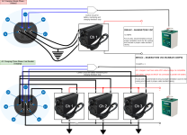
This design is compatible with both 1-ph (which make up the majority of chargers in my area) and 3-phase EVSE if available. Charger 1 will always be running by default.
My questions
1) Is there an issue with 3 chargers sharing the same neutral line? 3- phase lines from the grid at 480 V will have 250 VAC when connected in phase-to-neutral, but EVSE output may implement higher safety tolerance as stated in the internal spec. In most other vehicles OBC, based on my research simply rectify all the Lines to DC and have its own GND without ever returning to neutral. However, this is 3 separate single phase systems.
2) On the DC side output that will feed the battery, how will the chargers on the network know when the battery is full to turn itself on standby mode? Will it happen together? Which charger will shutdown first? Given that compatible charger with battery selection and that all 3 chargers are of same volts DC output 48/60/72/84/96 VDC, are there safety or fire risk issues that I need to take note of with using 3 chargers?
Control circuit
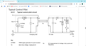
On the website Proximity Pilot and Control Pilot overview - PhilipMcGaw.com , there are 2 versions of the control circuit that can be used to initiate charging. The 1st one is a legacy circuit that can draw max 10 amps from the EVSE. Presumably, that also means 1-ph charging only
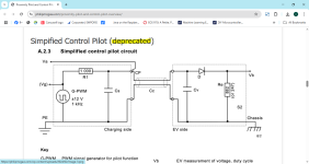
The 2nd image is a more updated circuit that allows "fast charging". 3 phase charging is generally considered "fast charging" due to the more power it provides. So I'll have to implement the new control circuit:
What are your thoughts?
This is my first post, so bear with me. Has anyone tried this config before either in terms of knowledge theory or practice? The idea is to utilize all 3-pins (L1 - L3) to separately power 3 AC e-bike chargers simultaneously for parallel battery charging. The chargers are off-the-shelf 220 - 250 VAC but high current (8 - 12 Amps) that will not be modified internally in any way.

This design is compatible with both 1-ph (which make up the majority of chargers in my area) and 3-phase EVSE if available. Charger 1 will always be running by default.
My questions
1) Is there an issue with 3 chargers sharing the same neutral line? 3- phase lines from the grid at 480 V will have 250 VAC when connected in phase-to-neutral, but EVSE output may implement higher safety tolerance as stated in the internal spec. In most other vehicles OBC, based on my research simply rectify all the Lines to DC and have its own GND without ever returning to neutral. However, this is 3 separate single phase systems.
2) On the DC side output that will feed the battery, how will the chargers on the network know when the battery is full to turn itself on standby mode? Will it happen together? Which charger will shutdown first? Given that compatible charger with battery selection and that all 3 chargers are of same volts DC output 48/60/72/84/96 VDC, are there safety or fire risk issues that I need to take note of with using 3 chargers?
Control circuit
On the website Proximity Pilot and Control Pilot overview - PhilipMcGaw.com , there are 2 versions of the control circuit that can be used to initiate charging. The 1st one is a legacy circuit that can draw max 10 amps from the EVSE. Presumably, that also means 1-ph charging only

The 2nd image is a more updated circuit that allows "fast charging". 3 phase charging is generally considered "fast charging" due to the more power it provides. So I'll have to implement the new control circuit:

What are your thoughts?
Last edited:


