408 threaded steel boss - Good an ya Crystalyte!

ElectricEd

100 W
Joined
Nov 21, 2008
Messages
265
Location
Belgrave, Victoria, Australia
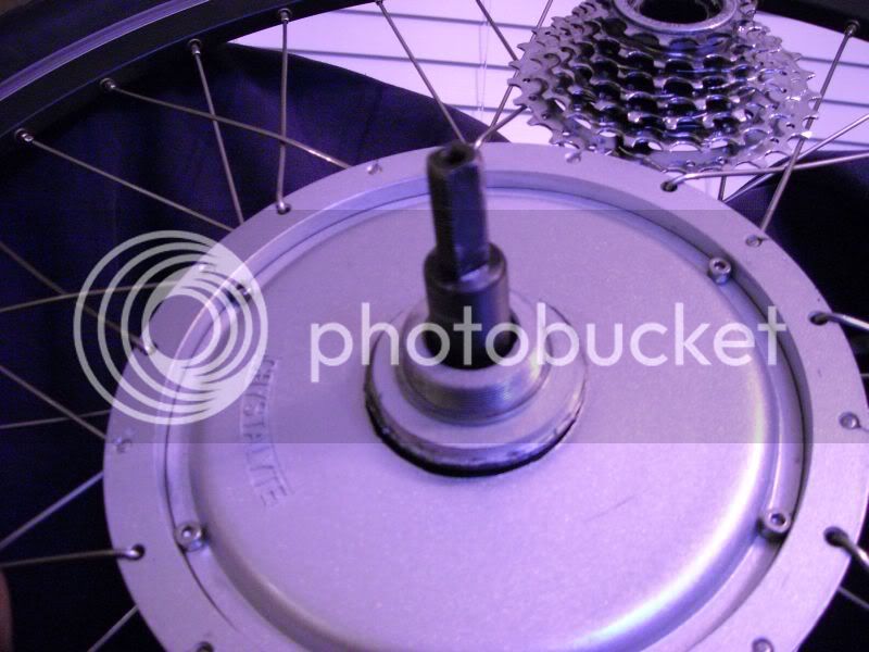
Wacko! I received a 408 threaded side cover from Crystalyte Europe recently as a spare. When I had a closer look it seemed to be a bit heavier than usual and had some surface corrosion on the threaded boss. Hmm. Out with the magnet...

408 Steel Boss Insert.jpg

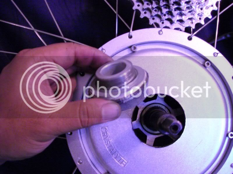
Adding to that, there's a seal inserted into the boss. How good is that? :D

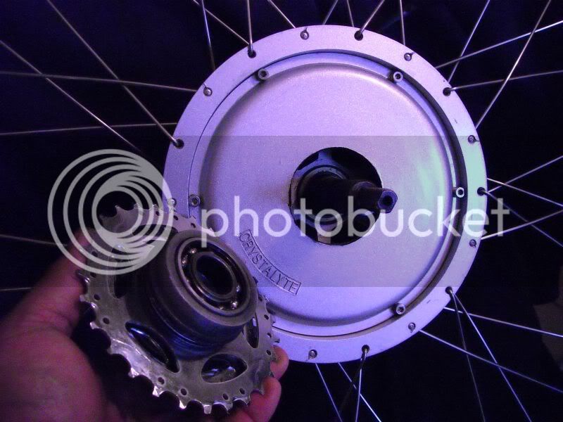
No more sheared off clusters. :)
One less place for water to get in. :)

Keep it up Mr Crystalyte. These are the sort of product developments that will get you to the top and keep you there. Well done!
 
Drunkskunk said:
Wait, are those the 6 bolt covers?
Damn, I have the 8 bolt style. :evil:

I bought it from Crystalyte Europe http://shop.crystalyte-europe.com/product.php?productid=16203&cat=263&page=1

There was a bit of a stuff-up with my order. I wanted 2 x 6-hole side covers but the first one that I received was the older style 8-hole without the steel insert. This didn't matter though as I have another 408 motor with 8 holes. The second unit came a few weeks later and had the 6 holes, steel insert and seal. Jef at Crystalyte Europe was quite apologetic. This is the only problem that I have had with them but fortunately it wasn't a problem. I find them to be very good with real information about dispatch and delivery times.

I get the impression that these new types only come with 6 holes. :(
Keep any eye on Justin's website, I had originally asked there but they were out of stock of 6-hole covers. If he is getting in new stock, they may be of the new type.

If you have a good square drill press and are careful, you can match-drill from an old 8 hole cover into the newer 6 hole type. Use some metal filled epoxy to fill in the unused holes.
2 holes will match already, you'll need to drill 6 new holes.
When you set it up to drill you'll need some shims to support the outer flanges as the internal bearing boss on the 8-hole protrudes past the plane of the flange...
408 Match-drilling.jpg

Use something more accurate as a base than the rough-sawn treated pine shown in the picture and use a shim on both sides of the hole being drilled.
HTH. :)
 
Nice! But does the new steel boss actually connect to the rest of the side cover with a good steel flange?
My 408 cover didn't break from the threaded boss... it broke at the face of the side cover itself.

BrokenHub1.jpg


BrokenHub3.jpg


BrokenHub5.jpg


BTW nice method of lining up the side covers and drilling out the new holes and filling up the other holes with epoxy. You got a pic of the finished product?
 
Sacman said:
Nice! But does the new steel boss actually connect to the rest of the side cover with a good steel flange?
My 408 cover didn't break from the threaded boss... it broke at the face of the side cover itself.
<Snip>
You got a pic of the finished product?

The pic was for demonstration only. A picture is worth a thousand words. I don't need to do it yet as my motor is the same as yours with 6 holes.
My older 408 with 8 holes is still OK. I operate on the boy scout "belts and braces" principal so always have a spare.

Here's a piccie of the inside of the cover. The extent of the steel is indicated by the tip of my (rather grubby) finger. It's 52mm in diameter. The Aluminium part surrounding it is 62mm in diameter...

408 Steel Boss Insert Size.jpg

One thing that does concern me a bit is if the motor gets hot, the aluminium will expand more than the insert, possibly causing a failure. If Crystalyte have done it properly the insert should be knurled or keyed in a manner that keeps it located properly within the aluminium. I won't know until it breaks though. :(
With the larger diameter of the internal boss, you won't get as much flexing of the sidecover so are less likely to have it break in the manner that yours did. It also has a larger fillet.
There's a pic of how mine broke at http://www.endless-sphere.com/forums/viewtopic.php?f=3&t=9205&p=143011#p142756
 
Sweet! The new metal DOES flange out along the face of the side cover. Thanks for the pic.
I also notice the 2 notched keyways (or large splines) between the metal and the aluminum which should help maintain toque transfer (from cassette sprockets, to face of side cover, to the rest of the outer wheel) even if temperature causes a gap between the metal and aluminum.
 
Sacman said:
... should help maintain toque transfer...

Here in Canada, anything that aids toque transfer is good...

Seriously, though, and I apologize for taking a detour... In looking at the close-up photos posted in this thread, and being enthusiastic about the engineering changes that Ed highlights, I couldn't help but notice the (traditional) way in which Sacman's wheel is laced. Every other spoke exits from the opposite side of the flange like a regular bike wheel, and there seem to be some serious "bends" where the spokes cross each other. I'm interested in this, as my 406 shipped with the spokes installed with ALL of the heads to the outside (this is a 26" wheel). The spokes ARE "laced", and with the standard 1X pattern that's typical of most motorized wheels, but I've always been tempted to re-lace this wheel because it seemed wrong. The spokes are in contact with each other where they cross, but don't look anything like the preceding pics.

One of those thing that makes me go, "hmmm"...
 
I forgot to mention a few of important things when I changed my broken 6-hole threaded side cover with an older 8-hole threaded side cover.
1) The 8-hole aluminum side cover came from Ypedal, who had a box of these laying in the back of his closet, and who also was gracious to sell me a couple dirt cheap.
2) The new 6-hole threaded side covers are 2mm smaller in diameter than the older 8-hole threaded side covers. I had to chuck up the 8-hole side cover squarely to my drill and spin it like a lathe. Then I used my Dremel to remove 1mm of material from along it's edge (effectively removing the 2mm across it's diameter).
3) Instead of drilling 4 new holes into the 8-hole side cover I drilled and tapped 6 new holes into the center ring hub (just outside of the manget ring).

And in reply to Philf's observation of my spokes... they are not original...the wheel was relaced. The cheap original spokes from Crystalyte kept breaking at a rate of 1 per week until I got fed up fixing them. I had my LBS just relace the whole wheel with GT Swiss spokes that are thinner (14 gage) but made of much higher quality steel. I wasn't happy at first when I saw it was relaced differently and with some slightly bent spokes but it turned out the guy who relaced em really knew his stuff. He explained to me the alternating spoke head at the shoulder is stronger because it keeps the spoke head pushed into the hub. Turned out he was right. I haven't broken a spoke since and I couldn't be happier with his work. Makes me wonder why Crystalyte didn't lace them up this way to begin with.
 
I just picked up my new bike with a BMC V3 1000 Watt. I was a little dismayed when I saw all of the spokes bent around each other wherever they cross. I thought the lacer had screwed up. I asked my dealer to take the wheel back to him and inquire if this was right. He did and reported back that the lacer is one of the best, really knows his stuff and laced it this way specifically because it makes the wheel stronger for high-power electric motor torque. I then found this thread. Any others care to make comments on how their high-powered wheels are laced? Is this normal practice or a good practice?
 
BVH said:
I just picked up my new bike with a BMC V3 1000 Watt. I was a little dismayed when I saw all of the spokes bent around each other wherever they cross. I thought the lacer had screwed up. I asked my dealer to take the wheel back to him and inquire if this was right. He did and reported back that the lacer is one of the best, really knows his stuff and laced it this way specifically because it makes the wheel stronger for high-power electric motor torque. I then found this thread. Any others care to make comments on how their high-powered wheels are laced? Is this normal practice or a good practice?

I hope the moderators will allow just a little more leeway on our discussion of wheel lacing because you bring up a good question which lacing is better. It was explained to me this way: If you think about the stresses on the spokes alone... the torque transfered from the hub to the outer rim via the spoke is distributed evenly thru all the 32 or 36 spokes. So each spoke is only seeing 1/32 or 1/36 of the stress force from the motor torque.

Now think about how the wheels hold the bike off the ground. The bike is actually SUSPENDED by the spokes.... in fact by one spoke only. If you cut off all the spokes except for the one vertical spoke that hangs the hub from the rim above it, the bike will still stay suspended off the ground. The tension stress on that one vertical spoke is high and more critical than the stress it sees from high-power motor torque. The alternating and 1-cross lacing helps the spokes to better handle that tension stress. And the slight bend in the spoke really doesn't matter that much because the spoke tends to straighten itself under tension anyway. Hope that helps.
 
Thanks! I just needed to know that this wasn't a massive error from some trainee lacer. They used a double wall Sunrims Rhyno Lite wheel with 13 ga spokes and eyelets.
 
Sacman wrote:
Now think about how the wheels hold the bike off the ground. The bike is actually SUSPENDED by the spokes.... in fact by one spoke only.

Ah, a common assumption. That's what I thought the first time that I tried to nut out how a spoked wheel works.
Consider, the spokes are at a high tension. If you sit on the bike and get someone to pluck the spokes you'll find that the lower spokes may be a little lower in tone than the upper spokes, but they are still under tension.
The load is shared by all spokes, but vary by the angle that they are from the vertical. The spokes that are not vertical also pull against the forces that are trying to squash the wheel. This is most on the horizontal spokes. There's a bit of trigonometry required to figure out the resultant forces on each spoke. You are right in that the upper most vertical spoke has the greatest amount of tension and the lower most vertical spoke has the least, but there is a sinusoidal variation in spoke tension as you go around around the wheel.
 
The update to steel might be more significant with regard to (hopefully) better alignment of the cover to the axle. I've seen hardened steel transmission shafts separate due to misalignment stress, as though they were cutoff on a lathe.

I would closely check the runout of the cover while it spins on the bearing. If it has significant runout, the cover may still crack; just further into the sidewall.
 
Sacman said:
Ithe outer rim via the spoke is distributed evenly thru all the 32 or 36 spokes. So each spoke is only seeing 1/32 or 1/36 of the stress force from the motor torque.

Now think about how the wheels hold the bike off the ground. The bike is actually SUSPENDED by the spokes.... in fact by one spoke only. If you cut off all the spokes except for the one vertical spoke that hangs the hub from the rim above it, the bike will still stay suspended off the ground. The tension stress on that one vertical spoke is high and more critical than the stress it sees from high-power motor torque. The alternating and 1-cross lacing helps the spokes to better handle that tension stress. And the slight bend in the spoke really doesn't matter that much because the spoke tends to straighten itself under tension anyway. Hope that helps.

the first part is absolutly correct for a radial laced wheel in refrence to drive torque. on a wheel with cross lacing, only thiose spokes with an angle 90 degrees or less to the lateral force are transmitting torque, the other half of the spokes are being pushed inward against the islaet, and there is no way for that force to be transmitted to the wheel. Spokes pull but can not push.

As for the hanging by a single spoke. No, but yes. that spoke has the highest tension, but its' acutaly a small percentage of the total. All the spokes on the top half of the wheel are supporting the weight of the bike
Think of a ball. run a string through the ball, then grab the string at both ehds with the ball in the middle. now pull your hands apart and you will hold the ball up.
the spokes on the bottom half aren't weight bearing. you can't push with a spoke, as the nipple would be pushed back into the rim and into the tube. and the weight of the hub would be pushing down on the bottom spokes, back into the rim, into the tube.
 
ElectricEd said:
Sacman wrote:
Now think about how the wheels hold the bike off the ground. The bike is actually SUSPENDED by the spokes.... in fact by one spoke only.

You are right in that the upper most vertical spoke has the greatest amount of tension and the lower most vertical spoke has the least, but there is a sinusoidal variation in spoke tension as you go around around the wheel.

That was the whole point in the "suspended by one spoke" statement... to illustrate which spoke will see the greatest (critical) tension load. I guess I could have phrased it better to not be misleading. But yes ... of course the remaining spokes do have tension in them... just less tension.

And to get back on subject to the threaded steel boss... TD might be right that the cover might still crack further up the sidewall but there's more material in that outer circumfernce so I'm inclined to think it would be less likely to.
 
Back
Top