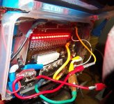
48v 15ah Ping batt hits LVC first time.

317537

10 kW
Joined
Oct 19, 2008
Messages
939
I want some feedback how my ping 48v 15ah batt is going.

My bike is a large MBT with thick steel frame weighs around 43kgs 95bs with battery Magic pie motor and accessories, today towing a 10kg (22lb) trailer with a 10yo boy in the back, he is slight build and maybe weighs only 20kgs (44lbs) I weigh 75kgs 165lbs.


Total weight, 148 kgs (326lbs.)

My back tire was a "little" flattish and forgot to test it on the pressure gauge, I went for the longest ride I do today and the wind was pounding much stronger than usuall and trees were tempestuosly swaying in the gusts, I face very little hills on my journey. I must of rode 20km (9.3mi) against the wind, maybe 15kms directly against the wind, and 5kms (3 mi) at an angle, My controller is set for 30 amps cont. And on the way home, was shorter and there was no wind at all, as it had stopped. So I estimate about 15km with no wind.

No pedals.

I made it but 500 meters from home and it started slowing a cutting out. I charged about 17.5 ah before one light on my BMS over the runt cell got switched on. and 10 minutes transpired charging at 2 amps before the all came on, maybe less amps at the end of charging cycle.. Usually all the lights come on within 10 seconds.

The pack is 22mths old and has been riden hard up to 15km-20km 7 trips a week often towing home a ton of stuff and I would usually do 9ah. On average about 662 3/4 dod cycles running @2c cont max discharge current.

I think the pack is still up to the task, but I might have to reduce the current draw to 1.5c.

So what shape do people here think my ping batt is in?

I think it did pretty good today as I havent really pushed it this hard for this distance before.

My Mrs isnt so optimistic though. She rides at max 14kms with a Low,medium load and drills it very hard 14kms from the Shops home.
 
Doesn't sound too bad for the type of use you are doing. You would expect less capacity at 2c, than you'd get at 1c. Surely you are discharging above 1.5c while climbing the hills, but it's not likely you pull the full 2c except at start up.

Got an ampmeter so you can tell what amps you really pull continous? Personally, with just me on the bike, I know pulling 18 amps continous is not going to significantly harm a 15 ah pingbattery. I haven't wanted to test my ping any harder than that. I'll see spikes up to 30 amps on the CA, but never really see the max 22 amps continuous. Expensive test for me, just to find out if it could take more, and for how long. I recomend what I've been doing as the upper limit, since I do have proof that it should do no real harm.

But I'm a bit confused, you put 17.5 ah into a 15 ah battery when you recharged? Is that measured before the charger?

It doesn't sound like your runt cell group is that much behind the others, if it takes just 10 min for the others to light the bms up. If it took 45 min, that would be a problem showing. If nothing else, the entire pack seems to be close to the same so you don't have a completely dead cell in there yet.
 
Phew thanx. Dogman, it just this hasnt happened before to me.

I set the cont amps it in parameter designer @ 30 amps. The 17.5ah is just a guestimate. I run a 5amp charger for 3.15 hours/mins and switched to the 2 amp charger when I saw the light. Then at 2 amps the light went off and it ran for another 40mins before the light came back on again.

Yeah this is why I say continuos max. Any where between 30 amps and I would guess with this load 22amps against the wind.

This new EB312 controller is weird, it has a lot of top end torque and gets me going at 45kph 28mph with out much trouble on flats. Never had this motor hit above 42kph on the samne tacho. I think Im running 110% speed setting. My CA started smoking over a year ago. I should test my current really.
 
317537 said:
I set the cont amps it in parameter designer @ 30 amps.

That'll probably be about 23amps actual then as the setting in the software doesn't usually correlate exactly to the actual draw.
 
what do you mean when you say your cycleanalyst "started smoking"?

in order to even know what has caused the cut off, you need to know what the current flow is.

when you say the 'runt' cell was the first one to light the led, that doesn't correlate to the 'runt' cell being the one which was most discharged, so that it would cause the BMS to shut off for LVC. one would expect the lowest cell to be the last one to light the led.

it may be possible to save the pack before even more damage is done but we would need to know what the cell voltages are when it is charging and then be able to monitor the cell voltages as the pack is discharged into a dummy load.

without info, there is no way to know which cell or cells may be giving you problems. or what the problem is. it may be possible to keep the damage now to a minimum if we knew more. the CA would really help with that.
 
By Runt cell i presume you are thinking the lowest capacity cell is the one that is recharged first, this may be the the case but it could also be this cell was at the highest voltage before charging started, i think you need to know the individual cell voltages before and after charging and some means of measuring the packs AH capacity to get a more informed veiw of its health.

We have a 36v 20ah ping running on one of our bikes (same w/h capacity as yours) it has performed brilliantly but recently stopped lighting one led on the BMS, we are working through the process of identifying why but it is looking like the pack is fine and it is just a faulty led, we do have a max amps draw set to 35a which is 1.75c but this is only occasionally reached briefly under full acceleration. My experience of pings is they do exactly as claimed if they are used within the limits recomended by Ping. We had a limit set to 30a for the first couple of dozen charge/discharge cycles. If you have done 600+ cycles on your pack then it is possible that you could be approaching a 10% reduction in capacity by now but it should still perform fully in all other aspects.
 
ping packs don't fail because the pack has been cycled multiple times, from my analysis of dead packs.

they usually fail when the tabs begin breaking. if one of the pouches is disconnected then it forces the other pouches into overcharge condition which then causes the other pouches in parallel to overheat and blow the electrolyte out through the tab seal.

of course he can continue running it until they also burn up but if he can replace the one bad pouch before the others fail then it will cost less to repair and less electrolyte corroding the other tabs.

but of course we really do not know anything at all about it until there is some real info. then he would know where to look.
 
In any case, I wouldn't sweat the amps draw too much, if you have had this motor and controller very long and nothing bad is happening. The slower speed winding motors I have tend to naturally have a lower amp spike than "normal" windings when starting up, and tend to run a lower wattage climbing a hill as well. It takes more hill to pull a full 30 amps than with a fast winding motor. Some of this is just because cruise speed is simply slower I think. So it takes less amps for slower.

I doubt the "runt cell" is overcharging, that would be more likely to be indicated by the runt cells bms light coming on first, long before the others. The "runt cell" may be your best cell, which takes more wh to fill up because it has a higher capacity. Or it could be the cell that runs your bms, and then gets discharged a bit more than the other cell groups.

In any case, if the bms lights all do light up, and at close to the same time, it indicates your battery is wearing fairly evenly, however worn it might be.
 
I ran the bike with no BMS for about 6mths only charging it to 3.5v per cell and it never went too far out of balance and never ran it flat. However I started noticing one cell always being lower to charge dropping under all the others. Well this was the first cell to charge last night.

Well charging last night my solder on my BMS was melting, so I stoppped the charging and ran a bypass wiire over the charge fet as it was burning up, so today I bypassed this fet with an IRF4110 with its own sink. Charging is fine now. When I took it on a test run this morning, all the other fets were burning up too, I think from the one closest to the charge fet. I hate BMS's.

So I made a fet bus out of 4 IRF4110 fets out of a dead infineon controller, I connect source to post BMS shunts on the BMS and removed all the old BMS fets, I connected the signal gates up and the output along where the old BMS fets were soldered to the board. Now no heat at all.

It cut out on a short ride today to the shops, it might of been the key switch, as when I tuned it on and off again, it worked, I rode it home and tried as hard as I could to make it cutout , starts on hills and what not. It seemed to be running well.

I havent got an amp meter that can do over 10 amps. But to say my CA one day just started smoking and almost caught on fire, it was working very well, I wasnt working on anything at the time and just one day I switched on the bike and it starter smoking, I dont know why.

The best I can do is a voltage load test ATM
,

I just did a load test then. After an 8km ride, I did multiple stop/starts up a grassy hill in the park and it didnt slump under 49v at the controller plug and jumped back up to 52v and rested at 52.7 , with all the connections and wires this is about as good as it gets.

The rest of the BMS works good . Im taking a picture of the mod I did. As to why the BMS fets started to get hot, it may of been one of those shorts circuits I did when building the bike 2 weeks ago, but it seem to work for weeks since that short circiut event. ?But anyway the 4110;s shall serve me well.
 
Here it is.


I know it looks ugly, the JPG makes it look much worse. Looking at the picture made me check the solders again with my 3.5 X glasses and they are solid as a rock. It was hard because I didnt want to pull all that out and did it where it was. It looked so good before the mod.

The charger fet source wire is soldered solid over the hole, That other bit was the old fet leg, I just sinpped him off then

Im neatening it up now and getting rids of the excess hot melt glue. I thought Id leave that little bit of glue over the screw on the main power bus to see if it would get hot and melt away after a good test ride and the glue was still hard. The fets dont even get warm.

I slowly discharged one cell after I installed the charger fet to see if I could trigger HVC while the rest were fully charged and the charge fet is working nice. Its the black heat sink.

The BMS or any of the bits I put in are platic zip tied by the main wires and a run of hot melt along the top keeps it snug, its been like that for a while now and happy with its mounting and doesnt budge. I could improve on this Idea but I just wanted to get it going and just made it up as I went.
 
No suprise your bms melts if you seal it up in a box like that. Or do you open it to charge, that's when it needs cooling most, while it's balancing. It needs a breeze, but I assume you live in a wet place.

On the CA, did you ever tell Justin about that? He gives darn good CS on those things, if you haven't done anything wierd like overvolting it, you might get a great deal on a new one. He may want to look at it enough to offer you a new one.
 
still no info. without knowing if the cells are dead it is kinda silly to worry about the BMS.

why is it that you cannot measure the cell voltages if you have a voltmeter?

if you ran it for a long time without a BMS there is no way that there is not a dead cell imo.
 
Well replacing the fets with the FB 43107 fets (not IRF 4110) Seem to put the BMS shunting out of whack. The 12v circuit run off the first four cells seemed to play up using these fets, and it would shunt early before the lights switch on and harder over the first four cells so they discharged before the other 12 cells. Its hard to replace fets when part numbers on each fet are scratched off, as to the point of that, go figure! Ive heard other mention this annoying problem, not to mention "yours truly".

On the contrary, I ran a signalab BMS in the foam box for a year without any issue, it is when I wanted to get air to it, is when it got damaged, I left the fet end of the bms poking out of my pack, Besides at the bottom of the lid if a vent hole. Air get in and no water. When loading the trailer the bike fell over and munged it. Simply no where to put it as I need to ride in all weather, not because its sunny old day and I feel like a ride.

Now I got all the boken BMS's and removed all the fets and tested them with a 2amp load to the millivolt @ 12amps looking for a higher resistance and chose the best 4 from the lot. Installed plugs so I can test different power fet configs and improved the design. Closed the box and went for a heavey ride. Got home, opened the box, Again no heat at all, or residue heat,. Charged @ 7 amps but today the single FB 43107 got toasty warm not the same as the otherday.

I can ride or charge with my finger on the fets with the box open and can detect a problem with in seconds.

If I showed the arc hole in my side cutters you might understand how I figured it was a short circuit i did that weakened the fets not the box. LOL.


So I removed two fets from an old GM controller, (IRF2807) tested them, and they worked. The BMS seems more forgiving swapping out the charge fets wirh different parts. Im discharging the bike to test the IRF2807 fets.

My original issue wasnt that I couldnt test the voltages as they seemed fine, I just wanted feedback on my ride and how the pack was doing in general and the LVC was normal, I since suspect the LVC and the bad discharge fet may, I repeat may of been an issue. Besides a volt meter is absolutly useless 20 minutes after I walked the bike home as the volts could well of popped back up to undetectable level.

Charging the pack without the BMS was fine I would regularry check the sense pins on a weekly basis and more then often they kept a nice balance and I never experienced and loss of power due to over discharging.

There are numerous reasons why I have a few broken BMS's one of them was the fact that the four pin sense wire plug on this pack are the opposite polarity to the replacement cables I was sent. Ping was more than willing to offer me a replacment BMS, even so, I paid for every BMS resuming the responsibility of not testing the cable before pluging in, or my goof ups. That was two BMS's I think died as a result of this oversight, Another was shorted to ground on the PCB another due to an a bike fall over, and another because I put too much pressuer taping it to the pack and some SM components popped off over time. And this one i suspect the dead short. Switching on and off and on and off again at the 60 amp relay I have, became a muddle in the wee hours. And cutting the power in bad light had me cut positive and negative together. ZAP, that was weeks ago.

Anyway Ive redone my charge and discharge mod again and now I made it so I can swap it out with some decent plugs Ive also added some more small holes on the bottom of the box to allow a little air in as I think the Melt glue was restricting the vent hole where it was.. I added the holes, ok. Whats the use of asking for feedback if your going to not follow the advise?

On my rides since the bike has been very powerfull and responsive and I feel the pack and BMS is working fine as it balances all cells now within seconds.

Again the feedback has been most helpfull, and I appreicate the company through this issue.

Pictures comming.
 
BMS2.jpg

Just sharing.

As you can see all leds are working indicating that none of the cells are taking on more voltage than the others. Just noticed that one of my plugs may have slipped the crimp. Its good to take pictures and examine abd share, digital zoom works so much better than my glasses.

I used epoxy to secure the gate legs from bending and breaking and the bus train is solid enough with plent of solder all the way up the source and drains leg.


About to do a 7 amp charge with box closed to test the heat after I gix that plug.
 
Excellent.

I must of discharged close to 2AH with wheel up off the ground runing WOT for an hour while posting 2 posts up. And it charged in about 20 mins @ 7amps, both IRF2807 were close to cold as ambient, which is around 10C ATM.

So when installing it i could trigger the gate by just touching the male plug end. operating the fet just from the current off my fingers. so the gates are working nice.. The hardest thing will be to test HVC, which will require charging one cell up to 3.9v while the others have rested to 3.3v and seeing if the charger fails to initialize. I suspect any of these optotransistors will ground these two parallel fet gates just fine, so I may even skip this test all together.

Next! can my two IRF2807 charging fets handle 9 amps. I have three perfectly well working ping chargers, 2* 2 amp and 1 five amp. They are most awesome I can couple the 2A and five together ATM and may add the other 2A charger.. I will admit that the aluminium these FETS are screwed onto and the two charging fets will be much better than the default BMS thermal design which is sealed with plastic shrink anyway when you buy the pack. Keeping them cool during peak loads will avoid them going into thermal runaway. . I want to run the bike hard tomorrow and test the 7 amps on a more discharged pack, and then I will go for 10 amps.
 
I wanted to add a tuning resistor to the discharge gates too so I can play around with LVC but wasnt sure if this would be appropriate not knowing the circuit so well, adding more resistance betweem the discharge fet gate and sense HVC LVC circuit might make matters worse using different fets.. I dont know really, the balance shunt circuit controllers seems to dependant on the total discharge fets gate resistance, as the discharge gate seems to feed off the forth cell controller chip to measure over currnet V drop over between the discharge fet output and the B- pad @ main shunt, if the ground gets too high off the output it triggers the fet to close. I lost track from front to back of the PCB and the Signalabs BMS schematic here is from the old BMS, and there are a few differences between the old and new design...

This is where I could of run into my cutout problem. It may not of been LVC, it may of been a sense of overcurrent discharge if one fet gave out on my journey and the voltage drop got too high between the B- pad and fet output. Unless I draw this up track by track, Im not qulaified to say really and googling the part numbers on this design usually turns up cryptic hits on data sheets, maybe Ping is protecting his design by scrating off searchable part numbers on the components. ..
 
dnmun said:
still no info. without knowing if the cells are dead it is kinda silly to worry about the BMS.

why is it that you cannot measure the cell voltages if you have a voltmeter?

if you ran it for a long time without a BMS there is no way that there is not a dead cell imo.

Just read more into this this.

Yes Im silly, maybe it was losing the fet that triggered excess waste of energy causing me to use more power per distance, or triggering HCC or LVC due to a higher vdrop between the B- and the output..

Playing with a failing BMS output maybe more onto my own topic than one may suspect. What Im doing here maybe better than just adding a thick wire to the ouput to draw the excess heat off the output with a failing fet huh?
 
leslie, i really cannot follow what you are talking about in terms of tuning, but i can see that all the leds are lit up, just don't know how far outa balance the cells go when it is being discharged.

you said it was cutting out. that is caused by the LVC of individual cells, and there may be an total pack voltage cutoff also, but the only one i ever see is the cell level LVC. if you have a cell damaged by overdischarge or overcharge then i would expect it to drop faster to LVC than the other cells.

this is what i suspected of causing your BMS to shut it down sooner than it once did.

if there was some way to know which cell that is, then you could actually look at the cell closely and see if the tab had broken already. that is how the pings usually fail, when the tab breaks off and that individual cell loses the 5Ah of capacity for the missing pouch.

the leds will not help with that because they only light when the cell is full of charge, not discharge. you have to measure the individual cell voltages when it shuts down so you know which one is the damaged one. it has nothing to do with tuning. the balancing voltage is fixed by the resistors in the voltage divider made up of those little surface mount resistors that the little 6 pin comparators on each channel monitor. it cannot be changed.
 
Well here's an update.

I finished testing the BMS. All the features are working now. I rode 32kms without a heavy load and it started to lose power still, I didn't want to LVC the pack. I still thought something wasnt right about it.

Puilled the whole damned pack apart, the way its setup it isnt easy, and just as hard to steal.


I saw no visual presence of a broken tab, And no puffy cells. This made me happy, but what if one series cell tab had broken inside the pouch?..

I thought if I put a good enough load over each cell between two voltage probes, Id find a bad cell block. I got some copper motor winding wire and Made a 2 equal lengths about 140cm long, stripped the insulation off the ends and made a long resistor.

I twisted the copper ends tight around the probes and dug them good into the cell tab soldering, testing the pack and creating a significant discharge load. I generated a V drop to 3.08v on each cell. What I notice is 2 blocks dropped lower than 3v

To further investigate, I had an old cell 20ah pouch block handy from an old 20ah pack, I recharged 5 mths ago. So ?I cut the two cells off, and ran the same load test. Sure enough, on the 2 p cell block it dropped to 2,98v. So I soldered one cell each to the top of each cell blcok that tested low. The last two load tests on the low cell blocks saw a v drop to 3.07 and 3.08 respectively. The two cell blocks I patched were behaving the same as the other cells blocks now.

I cant say whether or not it was a broken cell tab but it sure behaved like one on the load tests. I haven't tested the range just yet, but the quick run I did last night did feel promising. I felt more power in take offs and mid range torque. The pack took 7 hours to balance last night but balances fine now..
 
that sounds like a good fix. if the pouch that is bad drags down the others in that cell you can watch for it. but it may be a non issue if you were able to boost the capacity of the low cells. BOL
 
dnmun said:
that sounds like a good fix. if the pouch that is bad drags down the others in that cell you can watch for it. but it may be a non issue if you were able to boost the capacity of the low cells. BOL

Yer the voltages on all the cells seem to be normal when its half charged. I think this is just a patch to keep the pack going until I build a new one. What gets me, is that the voltage drop doing the load test on 2p 5ah spare cells > was the same as the low 3p cells in my pack. And after patching my low cells with a pouch each, the packs low cells behaved the same as all the better cells in my pack. The differences was @ loading in the .01v range after the patch. I must of been pulling some power through the copper to make the 15ah cells drop to 3.08v

I Just welded two robust 18' trolley wheels with chunky pneumatic tire on them, with a 1" threaded rod for an axle onto my trailer today.. Ive introduced some drag to my trailer. Im looking towards a 15ah Headway kit and running 40 amp peak this year. I'm looking forward for a more custom solution to installing this onto my bike.. The ping is a good battery but I am out growing it somewhat and they arent going to have the guts I require for the type cargo biking Ive evolved up to.


I'll try a range test this week, but this pack is going to be used for a spare E'bike in a few months anyway.
 
Back
Top