48v 4 amp charger gave up just as i finished my new build...

tony67

100 W
Joined
May 26, 2011
Messages
124
As the title says i had just finished my new build, a kona coiler deelux with my 1200 watt cyclone, i was charging my battery when i noticed it stopped sooner than it should have. I checked and sure enough the battery was at 75%, checked the charger and just the red light was on and the fan had stopped. When i disconnected the battery from the charger but left it plugged into the wall i have no lights. Now a confession, i had the current turned up to 4.6 amps and voltage turned down to 57v.
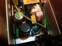
I have opened it up and found a few brown resistors however all still pass current and are not as bad as some i have seen.

I got to the charger very soon after it gave in and noticed it was VERY hot almost too hot to handle. Im wondering if its possible to diagnose the problem and fix it or just get a new one. Id like to have a go but my electrical knowledge is not up to troubleshooting this one. Ive read on here several people having success repairing chargers but any i have found had lights on when plugged into the wall. I have checked and i have voltage at the AC in plug and the fuse is good.

If anyone has any ideas id appreciate their input.
Cheers
Tony
 

Attachments

  • IMG_2394.jpg
    IMG_2394.jpg
    475.3 KB · Views: 1,187
  • photo.JPG
    photo.JPG
    60.4 KB · Views: 1,184
  • phhhoto.JPG
    phhhoto.JPG
    193.7 KB · Views: 1,184
  • phottto.JPG
    phottto.JPG
    62.3 KB · Views: 1,184
  • IMG_0152.jpg
    IMG_0152.jpg
    446 KB · Views: 1,184
not much to say, can't even see inside. all i am able to see is the missing clamp on the schottky diodes. what was the point of turning the voltage so low and the current so high?

ok more pictures now, so which is the resistor that you said was brown?
 
Here is a link to a very high res image. The forum limits to 512k images. I turned the amps up to get a slightly quicker charge and the voltage down because i don't run a bms and wanted to limit the risk of overcharging.

The large vertical resistor is slightly brown in the centre. The two to the right of that are brown but still check ok for continuity. Just above the yellow blocks on the RHS you can see another brown resistor, again it checks ok. I seen the two diodes that look like resistors on the RHS when i first opened it. Thinking they too were burned resistors i checked them and got no continuity so i removed them. It was only then I realised they were diodes so put them back. Thats why they look a bit odd.

Apart from that everything looks ok. I was hoping you might have some insight based on the increased current and no lights when plugged in because visually there is nothing remarkable to report.

Thanks for looking

 
Quite a few people here are familiar with these chargers. I'm not, but I can see the large yellow bagel is very well toasted. The honey drizzle is looking like black treacle. I see a cap there rated at 105c (which is a typical high temp value) but still, that kind of heat is over spec. I would look closely around there, and find what drives it. I assume the devices bolted to the shell. This is presuming it's a transformer not just a choke as these are so damn noisy (electrically).
 
good thing your charger burned up then if you don't use a BMS. having a lower charging voltage has nothing to do with overcharging the cells. charging wihtout a BMS to protect the cells is guaranteed to ruin the cells.

but the 6A may have been too much. so that gives you a chance to install a BMS on the pack. while you fix the charger.

i could not tell which resistor you meant was brown but the leak down resistor on the output seemed discolored for some reason, is that what you meant?
 
A word to the wise, if you are deeply into tinkering and doing things that are out of spec, consider buying two just in case of this situation. It sucks being stranded on an entire idea over a single piece of the puzzle, as I am sure you have concluded. My advice is, if this charger is wrecked and you plan on doing more tinkering (and maybe even if not), buy two.
 
If you don't run a bms, you'd be well advised to have a charger that easily single cell charges a low cell. For that, an RC charger can be ideal. Even a cheap, slow 50w version can top up your low cell from time to time. Just set it for 1s, lifepo4. Use it to bring up your low cells after a bulk charging is complete.

Or, depending on what you have, you could balance 6s or more at a time, using the "bms" built into the charger, as needed.

IMO, you need two new chargers, one a bulk charger, and another to help with balancing when you choose to balance. You can use a phone power supply, but that's a bit too manual for me. An RC charger will bring up that low cell and stop at the right point, without you having to hover over it.

He is correct, that if you let the pack get out of balance enough, you can still have overcharging of the highest charge/lowest capacity cells. If you don't need the range, undercharging can be helpful. If nothing else, gives you some wiggle room at the top. But don't just assume all is well bulk charging naked.
 
bowlofsalad said:
A word to the wise, if you are deeply into tinkering and doing things that are out of spec, consider buying two just in case of this situation. It sucks being stranded on an entire idea over a single piece of the puzzle, as I am sure you have concluded. My advice is, if this charger is wrecked and you plan on doing more tinkering (and maybe even if not), buy two.

nope you are wrong. by failing, his charger has prevented him from destroying his battery when he first charges it up. this is his only chance to get it right because his first charge is gonna ruin a buncha cells. he has no clue and there is no indication he ever did anything to balance the cells before putting it together. this is his only chance to put the BMS on and protect the battery from his misinformed opinions.
 
dnmun said:
bowlofsalad said:
A word to the wise, if you are deeply into tinkering and doing things that are out of spec, consider buying two just in case of this situation. It sucks being stranded on an entire idea over a single piece of the puzzle, as I am sure you have concluded. My advice is, if this charger is wrecked and you plan on doing more tinkering (and maybe even if not), buy two.

nope you are wrong. by failing, his charger has prevented him from destroying his battery when he first charges it up. this is his only chance to get it right because his first charge is gonna ruin a buncha cells. he has no clue and there is no indication he ever did anything to balance the cells before putting it together. this is his only chance to put the BMS on and protect the battery from his misinformed opinions.

I am not sure what you mean by wrong. The idea is, when something breaks, it may take time to fix it at best. When something is destroyed, it will need to be replaced. People don't keep a second transmission or engine for their combustion engine automobile because they wouldn't know how to swap them and the cost would be obscenely high. I am not suggesting he refrain from tinkering or asking questions, I am saying a good game plan, especially when you are pushing things to their limits, is to have a back up.

I am also not trying to say that making mistakes isn't part of learning, taking chances can often be a rewarding part of learning. Think of it like this, when a couple is going to have lots of sex, do they have a single condom on hand or a box? I am merely trying to illustrate a philosophy of being prepared. Situational readiness is a good thing, it doesn't prevent you from learning or making mistakes, situational readiness sets you free.
 
no, the battery is worth far more than the charger. the charger can be replaced or repaired for a few bucks but the battery is worth hundreds and hundreds especially if he used these expensive A123 cells so if he can get the BMS wired up before he charges it then he can protect the battery from his own mistakes. he is just misinformed about how to balance and protect a battery. there are a lot of people here who are deliberately misinformed that they can make a battery and use it without a BMS to protect it. there are alotta people who lose a battery because they had no BMS to protect it.
 
Ok we got a bit off topic partly because I didn't include certain information about my battery, but my question was about the charger. I'll try clarify. I reduced the cutoff voltage on the charger to 57.6V and increased the current to 4.6amps all measured through a turnigy watt meter i keep inline with my charger.

The reason I reduced the voltage was because i am not running a BMS and i wanted to under charge each cell, however I failed to mention I have added 3 jst balance leads 2 x 6s and 1 x 4s and with these, I have 3 battery medics which I set the discharge voltage to 3.6v. The idea being having been initially balanced, the pack charges in bulk, as each cell reaches 3.6v the medics (in discharge mode) keep them there while the rest catch up. This means my pack is balanced at every single charge and as the pack reaches 57.6v the charger switches off leaving every cell at 3.6v (slightly under charged). I think this is a good solution for those that don't want a bms.

I done it this way because when I was building my pack, I burned out a €70 BMS, more than likely through my own mistake (we all have to learn somehow), but I decided this was the route for me at that point and it has worked for 18 months and only cost €35 to implement. (BTW I said this was a new build not my first build) while my ability to diagnose and repair a charger is obviously lacking, I assure you i am very well informed on how to put a reliable bike together battery included. My 10 ah headway has just over 10000kms on it and still gives over 9ah when it is occasionally pushed. I didn't think the details of my build were relevant to why my charger died.

Anyway I thank you all for your input. I think i'll put this one down to experience and move on. I have ordered a new charger and will learn from this mistake, I will leave the current where it is, may even reduce it slightly. Sure whats the rush.
 

Attachments

  • DSC_0091.jpg
    DSC_0091.jpg
    295.7 KB · Views: 1,119
the chargers can be repaired. do you know how to test the transistors? sometimes i fix them and they still have problems too. but sometimes they work actually most often they work. this charger uses the small npn switching transistors though so higher current is a problem i think.

but your battery medics will let you charge it to full charge at 58.4 too. it is just hard for a BMS to balance when the final voltage is that low so we raise it higher for the bulk charger with a BMS, but not much.

the medics take power from the entire 6S as i recall. but it will give an alarm when the cell overcharges so you will know when to stop the charger. but they can charge up to 3.9V for HVC. most BMS based battery makers balance their packs to 3.6V
 
dnmun said:
the chargers can be repaired. do you know how to test the transistors? sometimes i fix them and they still have problems too. but sometimes they work actually most often they work. this charger uses the small npn switching transistors though so higher current is a problem i think.

but your battery medics will let you charge it to full charge at 58.4 too. it is just hard for a BMS to balance when the final voltage is that low so we raise it higher for the bulk charger with a BMS, but not much.

the medics take power from the entire 6S as i recall. but it will give an alarm when the cell overcharges so you will know when to stop the charger. but they can charge up to 3.9V for HVC. most BMS based battery makers balance their packs to 3.6V

I've never done it before but I have just googled it and it looks doable. Can they be tested on the board or do they need to be removed? Also would i be right in saying the components clamped to the case are not transistors? Forgive my ignorance :oops:

I need to try remove the board from the case in order to access the underside, a lot of silicone has been used during assembly making removal a challenge, don't wanna break anythin else.

The problem with the medics is you can only set the discharge point in increments of 0.1v so either 3.6v or 3.7v. Like you said this battery cost a lot of money so I baby it like you wouldn't believe. I think at 3.6v per cell I'm getting over 95% capacity which is more than enough. I read before those last few millivolts hold very little capacity.

The medics only bleed off very little current and so will not keep up with a badly out of balance battery. I know this because i discharged a few of my cells too low during initial manual balancing and thought I could rely on the medics to hold the others back while they caught up. Unfortunately the charger was still putting out too much current and the other cells started to run into the 3.70s. I stopped and brought them up with a single cell charger. This solution relies on a relatively balanced pack to begin with and from then on it will keep it there because every discharge/charge cycle sees one balance period meaning the medics don't have to do much bleeding and can keep on top of it.
 
the transistors are over on the side next to the rectifier diode on the fron end. i saw you had removed the clamp on the schottky diodes, and once you remove the clamp on the npn switching transistors and the rectifier sometimes has one but not on this little one i think.

then pull the transistors away from the sides and cut the glue joint along the bottom so it can be freed up. i use a utility knife and cut along the top and bottom of the polyurethane caulk and when you use the utility knife it will catch on the little legs of the wires on the underside of the pcb so you have walk the knife around and over them while cutting, and cutting along the bottom where the case is just stick the knife blade right along the surface of the case all the way through the goop. then take some needle nose pliers and grab one end and pull the whole plug out from the end. you gotta cut more where the pcb slides in the groove on the side of the case but eventually it will get free.

when the transistors and diodes are leaning in and the choke to case goop is cut then slide the entire thing out onto the bench. don't let the transistors pull the rubber insulator along with them, it has to stay there on the case where the transistor goes so make sure the transistors are leaning over and not touching.
 
Had this story end with any success?

I have absolutely the same problem, and almost exactly the same charger. While I hadn't modified it in any way, but it just quietly stopped charging. I also don't have such apparent burn marks on the resistor, but now I can assume that the strong smell of some fried Ohms rises from it.

My ICL is absolutely (and maybe unfortunately) is fine and reads approx 5 Ohms.

Ah, and both fuses are OK, of course.

I also believe I've found the scheme of it, or it looks very much like it.


dnmun what do you think?
 
Of course I did. How do you think I counted two fuses? :)

Now I had courage even to measure that I have 220AC at the board after ICL. But definitely, today I'm going home by metro train...
 
Symptoms all the same - it looks like no DC been converted. Leds of course dead. My thoughts went as follows - first I checked tl494 (as only IC I could recognize) - pins 7 and 12 - no voltage. Then I found the scheme and discovered 7812, tested - nothing on input, nothing on output.

Do you mean those in red circle? Will give them a try, but I'm a bit nervous about trying to reach them with probes having 220AC stalking around the board...

 
your AC voltages are in the front end. there is 340V DC on the caps and transistors on the front end. put the black probe on the - output and the check for 20V DC on the diodes behind the transformer. two of them should show voltage.
 
Checked - absolutely zero. While 220AC was still there (I rechecked again).
 
Measured resistance on transformers:
main - each pair from one side reads ~0.4-0.5 Ohm. I suppose that's very wrong?
secondary - high side: ~15 Ohm each, with one exception that reads 0.3;
low side - all 0.4 (or should I call it a shortage?).

UPD Tested transistors. One showed very familiar 0.4 (I definitely accept it as a shortage) anyway between the collector and other electrodes. So I decided to test it separately and unsolder it (vacuum suction pump comes very handy here and those are cheap). Looking closer it appeared that one leg was dim probably due to a flame\smoke, that passed nearby. And indeed - there was a tiny crack with melted sides on the trans. Needless to say, that all legs are shorted.


Second one appeared to be in better state, it looks anyway like diod with multimeter between the collector and emitter, but, alas - base was shorted in both directions.

I have some apparently suitable BUT56A at hand, but I'm not very eager soldering them, since transformers didn't change their mind and still show some strange values.

Have no further ideas for now.
 
I got access to the working charger of slightly different device. But transformer there showed some fractions of Ohm as well, so I decided that mine is fine. I soldered good transistors, but with no effect. Then I payed attention to the low value resistors on the transistors bases. They appeared to be dead as well, with no visible sign of it. I have no 0.5W 2.2 Ohm resistors, so I soldered pair of 0.25W 4.7 in parallel. Now I started to see some signs of life - I get 3.4V on output, and some humming sound with increasing frequency from somewhere on the high volts side. Also transistors get very hot, so I plug only for a few seconds.

Case stuck once again, need assistance.

UPD Red led lights up - hadn't noticed it at first. Two things concerns me most - that humming sound and very hot transistors, while battery is not connected. Also I read only the same 3+ volts on the diodes after transistor.
 
Interestingly enough, when I tried to power it up in the morning, it showed no signs of life again. Quick check found that base is shorted with collector in Q1, just like before the replacement. I'm out of power transistors for now, and have no idea why it fries out...
 
Back
Top