A123 20AHr Pouch Cell Battery Build & Info Thread

bigmoose

1 MW
Joined
Aug 6, 2009
Messages
2,675
Location
North coast USA
I thought it might be worthwhile to have a single thread of ideas and info for all the folks about to build or building batteries with the recent purchase of A123 20 AHr Pouch Cells lately. If you think this is a bad idea let me know, and I'll merge this thread with where folks think it ought to be.

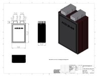
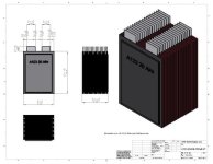
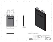
I'll start it off with some .jpg's .pdf's and Solidworks models for a single cell, a 12 cell stack, and an 18 cell stack. I don't have my cells yet to personally do the measurements, but Dr Bass did them and hopefully I copied them correctly into the solid models.

a123-20ahrcell-v1 (600 x 479).jpg
View attachment A123-20AHrCell-V1 - Sheet1.pdf

a123-20ahr-12cell-v1 (600 x 464).jpg
View attachment A123-20AHr-12Cell-V1 - Sheet1.pdf

a123-20ahr-18cell-v1 (600 x 464).jpg
View attachment 4

The three Solidworks solid models are in the zip file.

View attachment 3

Post licensed under the Creative Commons Attribution-Noncommercial-No Derivative Works 3.0 License
 
Before you build your pack you might want weed out the bad cells with a boUnce back test that nasa uses
 
NASA LiPo bounce back test in this document: http://ntrs.nasa.gov/archive/nasa/casi.ntrs.nasa.gov/20120000040_2011025423.pdf
on pages 11 to 14

Procedure is basically discharge your cells. Let them sit for a week or two. Any cells that bounce back in voltage then start declining in voltage should be scrapped.

EDIT: Didn't see that flathill posted the details in another thread. He said:
Another good method to weed out bad cells is a bounce back test Do a deep discharge and then plot open circuit voltage for a couple weeks Cells with soft (high impedance) shorts are b grade or should be tossed. ... In this report vendor #1(a) is a123 and you can see why they are going out of business (garabge qc) Note the wh/kg figure for the a123 is confirmed inflated The korean cells come out on top. You can see why luke picked eig cells for the zero bike
 

Attachments

  • NASAbounceBackTestLiPo.pdf
    1.7 MB · Views: 882
Thanks for uploading so we have it forever. It will be intersting to see the results of this test on victpower cells. Previous wisdom was to fully charge and then leave the cells for a couple days to see which had the highest self discharge. The Nasa method takes a week minimum

Even if a few cells are bad you cant beat the price on these a123 cells...at least until we can get our hands on a crashed 2012 hybrid car :wink:
 
FWIW- I have not built any packs from A123 cells. I have however just recently completed building 6 packs of 6each 16AH Dow Kokam Lipo cells which is pretty much the same challenge as building packs from the A123 cells. I built the packs in about a week before the Grange race last Saturday. I have generally gotten good feedback on the construction style and so far it has been working very well.

I am using clamping spacer blocks. The blocks were CNC machined out of HDPE on a vacuum chuck in a VMC. HDPE is not the optimal material, I believe- I was hoping to use polycarbonate or acrylic which are harder and less ductile/creepy... but I was short of time and HDPE is really quick and easy to work with (no coolant required while machining, fast to machine because it's so soft). As well in this completely compressive-strength application I don't expect creep to be a big issue. The clamping screws are #10-32, threaded into fully threaded round standoffs (.250 OD) Button head screws were used for lower profile. The "load spreaders" on the outside are strips of 1/2 inch wide, .062 thick spring steel, cut with an abrasive saw and drilled using cobalt bits- each bit only good for ~15-20 holes. Spring steel is hard! The screws are loc-tited into the standoffs- one side with red, the other with blue (overkill? maybe) and the spring steel should help distribute the force over the tab, as well as keep it tight like a belville washer would. Just under the steel spreader is a plastic piece with that is thicker in the middle of the tab and thinner toward the edges in a radius (surfaced on the CNC mill).

The tabs are about .008 thick. I picked .016 copper sheet to make balance tap points (for the series connections where the tabs directly lap) and pieces bent into U-channel shape for the series connections where the tabs are further apart. I built a small bending jig out of aluminum for use on the arbor press to bend the copper into the U shape with the right spacing and shape. Basically just a block with a groove and chamfered edges, and a mating piece that fit down into the groove with a bit of clearance on each side for the thickness of the copper, with rounded edges. Just place the copper on the bottom piece with the groove and press the top piece into the groove, folded the copper up perfectly.

The cells are taped together with Scotch double sided 109 "wallsaver poster tape" which is reasonably thin and has a relatively low level of adhesion, plenty of shear strength to keep the cells from sliding but should be easier to unpeel if need be. I used two strips the full length of the long side of the cell between each pair of cells.

The key in assembling these packs was liberal use of Kapton tape- it's super thin (~.002) so you don't have to worry about perfect wrinkle-free or even coverage and it allowed me to build the stack of cells one at a time, taping the copper pieces and tabs together without worrying too much about shorting because everything already built is covered in Kapton tape- then afterwards slide the clamping blocks over the top and tighten them. As well I wrapped the standoffs that travel through the stack with Kapton tape to reduce the chance of the block shifting to the side and shorting down the stack during assembly- it's thin enough that a wrap around the standoff still allowed the standoff to go through the .010 clearnance holes in the blocks. Even with the insulation on the tabs and standoffs assembling these packs is a stressful experience that requires a lot of concentration--- there's no way to "switch them off"... they are always "live"! I used a crapton of Kapton tape... Or since it came from sketchy Dealextreme, maybe it was actually in fact Krapton tape...

I was very happy with the outcome of the clamped blocks- mechanically coupling all the tabs together into the blocks keeps the assembly very stiff- it is virtually impossible to move the clamped blocks with respect to the cells- this is good because I would not want to have the tabs being bent and unbent in normal operation- it would be bad to stress fracture the tabs and end up with a high resistance spot! I feel reasonably confident just given the feel of the clamped blocks that this won't be an issue.

Finally I placed a couple strips of gaffer tape over the clamping blocks to give the exposed Kapton taped bits a little extra abrasion resistance and put the packs in boxes made of Corplast and put together with Gorilla tape. Balance wires were terminated with JST XHs (the devil... did this job in the passenger seat while driving down to the race...) and main positive and negative with ring terminals, #10 screws and nylocs, 10GA wire and PP-45s. For mounting on the bike I took some .055 aluminum plate and bent it on the box and pan brake to form a "4 sided" box- box with back, sides and bottom, no front or top. These boxes were screwed and pop riveted to the bike frames, then a bit of nylon webbing and quick-clippy bits to strap the packs in. Worked great, even crashing the bike a few times nothing has come loose.

So, I don't believe this approach is perfect, and obviously it's pretty labor intensive! But hey- at the end it's completely un-buildable to allow the cells to be built again in a different way if that is required later on. The only permanent change to the cells was trimming the tabs to .625 long- which I figure I will not need it to be any longer than that for any of the other termination approaches I considered as well!

I'm sorry, I know this is a dense wall of text and not completely clear. I'll post a few photos here and you can peruse the rest in the album on Picasaweb https://picasaweb.google.com/106371422363746314682/DK16AHBuild#

DSCN0260.JPG

PackAssembly4.JPG

PackAssembly1.JPG

IMG_0187.JPG
 
Also there is JD's spot-welding approach http://endless-sphere.com/forums/viewtopic.php?f=14&t=29959 which I think is pretty interesting and appears to work well enough in his experience (an important qualifier!) but definitely requires full and absolute commitment! Given the current low price of these A123 cells I would be more willing to consider trying a non-reversible and high-impact approach like that!
 
You can also solder alumium
Not easy but super light
IMG_1424%20copy.jpg

If you scrape the tabs with a chisel tip soldering iron you will break the oxide layer so the solder sticks
Scrape in a pool of solder in small sections so your tabs are "tinned"
In the pool it wont be exposed to air
Dont try to tin the whole tab at once or you will cook your electrolyte
More info
http://endless-sphere.com/forums/viewtopic.php?f=14&t=32762
 
Here is my 2011 thead on spot-welding a123 tabs:
http://www.endless-sphere.com/forums/viewtopic.php?f=14&t=29959
Edit oops I see acuteaero already linked it, thanks!

Here is my 2010 thread on Crimping a123 tabs, tested to 100a.
http://endless-sphere.com/forums/viewtopic.php?f=6&t=12461&start=60#p281360

I am working on a 48s 6p pack to upgrade the one in my VW bus conversion, cells in DHL as we speak. I plan on putting 3/16(?) aluminum spacer blocks between the tabs of the 6p cells, as well as the 6p of the next cell in series. Each spacer block has 3 holes in it, aligned with holes punched in the tabs of cells, and the holes in the bottomost block are threaded to accept a bolt. When the last cell is stacked on, slide bolts through the three holes to the threaded spacer block, and tension. A block of plastic with three holes drilled half-way through slides over the heads of the hex bolts, and insulate it from the threaded spacer block on the next set of cells.

-JD

flathill said:
You can also solder alumium

I got 9 cells from cell_man that he had tried to solder together, when I bought out all his scrap cells. He shipped them that way, but the solder peeled right off during shipping.
 
flathill said:
You can also solder alumium
Not easy but super light

One tab is aluminum, the other is nickel or tin plated copper.

There are special varieties of flux that can be used to more effectively solder aluminum.

Because aluminum and copper are good conductors of heat the challenge becomes to bring the tab up to solder melting temperature without allowing enough heat to enter the cell to harm the glue seal at the point where the tab enters the cell. I personally decided that advantages of soldering the tabs (compact, light, cheap) did not outweigh the expensive, dangerous risks (messing up the cells).
 
acuteaero said:
FWIW- I have not built any packs from A123 cells. I have however just recently completed building 6 packs of 6each 16AH Dow Kokam Lipo cells which is pretty much the same challenge as building packs from the A123 cells.

Nice job, I like what you are doing.

-JD
 
oatnet said:
Nice job, I like what you are doing.
Thanks!


Also worth a look for inspiration is j3tch1u's clampy-setup with neat machined frames.

http://endless-sphere.com/forums/viewtopic.php?f=28&t=15233&start=270#p345367

-Henry
 
Thanks, I forgot about Ben's solution.

acuteaero said:
oatnet said:
Nice job, I like what you are doing.
Thanks!


Also worth a look for inspiration is j3tch1u's clampy-setup with neat machined frames.

http://endless-sphere.com/forums/viewtopic.php?f=28&t=15233&start=270#p345367

-Henry
 
We should probably include agniusm's kit solution that he is developing. It seems to be the only manufactured kit available for 20AH A123 cells.
otherDoc
 
That is nice setup !

Question, I would like to buy 22s A123 20ah from Victpower, they also sell a 50-80A BMS for 98USd
But do I need a BMS when I monitor my cells just like the Hobbyking Lipo ?

Will they stay in the same balance when charging/discharging like the hobbyking lipo ?
 
I'll be building up a 24s pack for myself and a buddy. Even just a routed fiberglass board would help keep things neat. I surely want to bolt things together!
 
I think any means to clamp them between some copper and some brass with stainless steel bolts is a winner. Thread the brass to reduce the need for a captive nut (which will only drop somewhere you don't want it to) and the rest is paperwork. Soldering aluminium is just not worth it. Spot weld some copper to it if you really want to solder them. Mrs Wifey has been making noises about wanting a small car, so I said OK, only if it's electric. She was cool with it :) SO it would be A123s or nothing.
 
I was thinking of just using the Jack Rickard method, and building 10 cells into 3.3v 200Ah modules, then simply connecting them with those copper braid links.

At charging time it would be a doddle to bulk charge and then balance each one separately.

Obviously this would be for a vehicle. Just my $0.02
 
Yeah for parallel cells the work to install them is a bit easier and Jack's methods look pretty good. Unfortunately many of us want and need to do series cell connections and that is where a kit like agniusm is making will save a lot of work. It also obviates the need to try to put little teeny weeny bolts and nuts in places where I know I will drop them many times! Old age means more fumble fingers!
otherDoc
 
thanks for starting this thread... i'm involved in a ev project, and we are looking to use alot of these cells to construct a 300v 140ah+ pack for 2000amp peak discharge

keep your ideas comming!!!

-steveo
 
Back
Top