A123 20AHr Pouch Cell Battery Build & Info Thread

999zip999 said:
Oatnet what amps can the 4 rod aliumun block drutludge build safely carry ? Hopefully 65amps ? Crimping has a lot of surface area.

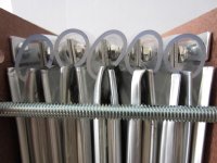
65 amps based on a large amount of clamping area should be fine, but the clamp needs to start very close to the top of the cell body. If you rolled up the tab across its width, it would make a pretty thin wire, so you want this part to be as short as possible.

The cross-section of the tab - width x thickness - is the choke point of current carrying ability, so all you really need is a contact patch as small as that cross section. A larger contact patch buys time as it means the join would have to really degrade before it becomes the choke point, and helps pull thermal load off the tab material.

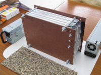
However, If you look at the drutledge pic below, I have concerns arround the bare tabs underneath the clamping blacks. First, vibration of the clamping block assembly will eventually stress crack the tab material, which is carrying that mass. Second, it looks like one could push the clamping assembly down or to either end of the pack, and cause the tabs to short out against each other or the cell body. Third, the distance between the clamping block and the cell tops leaves a lot of tab material to carry the current, sorta like leaving long FET legs, so I would be concerned at higher discharge levels.

Moving the blocks close to the cell body would eliminate concerns 2 and 3. It would require punching holes in the tab material which does absolutely nothing to reduce the cross section I mentioned, or reduce the tab's current carrying ability. However, I don't have a good suggestion for supporting the clamping block's mass, and I am not a fan of the weight it adds to the pack, so while I considered it I never implemented any designs along this line.

-JD

file.php
 
Pic I guess that is why Ping put a insulator there it looks like he uses black foam you can buy at home depot. I had some from ? the window door departmen with a sticky back. My 12s packs are almost supended in a clamp of yoga mat and tupperware lids. But yes JD the whole mass of blocks can be moved with desire. Don't like that pic now. It's along road.
What where those A123 28s3p packs made for ?
 
Now you making me think of how a different part of where my battery is challanced . The pessure on the cells is not flat but with the bow of the tupperware lid it puts persure on the four corners of the cells in the pack. Those end plates on your 28s3p would work if I could get my hands on them but would add width ? And is pessure on the cells needed for a low amp battery ?
 
Individual cell insulators whole height of cell are recommended anyway, with yours they could extend up to the clamp blocks, no risk of shorting and at about 1mm would even out the cells.
Once the whole battery assembly is in its enclosure and trapped, there's little issue with movement anyways, all id be concerned with this build is clamping pressure, as the pressure is the only variable in current carrying capacity up to where the pack requires tab thermal management.
Still trying to understand it as mine is the same issue eg the pack has a single clamping arrangement.
 
As a 12s block pessure from the four bolts I guess is enough but longer strings at some point will be a problem to ply perssure but at what lenght ?
 
Here is my preliminary build. It's not finished yet. I am still waiting on the wire connections from Hobby King. Anyway, my build used the short 10mm tabbed cells from Victpower. I clamped the tabs with 1/8" thick by 1/2" wide aluminum strips. I used 6-32 x 3/8" stainless steel button socket cap bolts, lockwashers and nylon insert nuts. Only the end tabs have holes drilled in them mainly because I wanted a separate connection for the balance wires from the charge and controller wires. I plan to replace the masonite with polyethylene. The positive and negative end tabs are clamped to the end panels. The end panels are bolted together to provide clamping pressure to the cells. The 5/8" OD x 1/2" ID vinyl tubing made for safe and easy mechanical connection of the tabs. Finally I intend to wrap the pack with 1/8" and 1/4" rubber flooring material shown in the photo.

I will be taking apart the entire pack once the wire connections arrive and to replace the end panels. I'll post more photos then.

My goal was to provide a simple, easy to build, low cost and safe process to build the cell pack. I cut the aluminum strips with snips. I used a drill press to help align the tab holes. Then it took about an hour to clamp all the tabs covering each tab with vinyl tubing as I progressed to minimize the chance of a short.

I think this addresses many of the concerns in building a pack. I plan to use this pack for a recreational e-bike at 30amps. For more vibration protection, I would drill a hole thru the middle of each tab and add a nut and bolt. I wanted to avoid drilling holes in my tabs particularly since I only had 10mm tabs to work with and the negative tab already is full of holes. So my clamping pressure is close to the cell body and the tabs are supported and isolated from each other with the vinyl tubing. The pack currently weighs in at 16.5 lbs.

I would appreciated any feedback you might have. Most of the ideas for this build came from viewing all the other builds made by members on this thread. So my thanks to those who came before me.
 

Attachments

  • build8a.jpg
    build8a.jpg
    344.2 KB · Views: 2,106
  • build9a.jpg
    build9a.jpg
    298 KB · Views: 2,105
  • build12a.jpg
    build12a.jpg
    302.4 KB · Views: 2,106
I think Ive sussed out what's happening in a single clamp build.
If the pack is clamped similar pressure to a pack with individual tab clamps, what happens, hope Ive got this wrong, the same pressure is divided across the number of tab joins :? Eg got to clamp the heck out of it for big amps.
 
Raygo I would put plastic tubes on those bolts next to the cells. What holds the split tubes in place over the tabs ? Maybe a pot of hot glue.
 
Actually, the vinyl tubing worked out much better than expected. There is a considerable amount of friction between the pieces of tubing. I thought the tubes would slide easily into place after I installed each tab clamp. Instead, I had to really work at fitting the tubes in place to the point that I had to install each tube without touching another piece. When you touch two pieces of tubing together, they stick like velco. Then when I clamped the end pieces together, that applied even more pressure to the vinyl tubes. The tubes stay nicely in place. So no pot of glue needed and disassembly will be easy for this type build.

However, I don't know how well it stays in place without the clamped end pieces. I think it will still work since the tubing is slightly wider than the spacing of the cells so that you do get compression of the tubes from the cells as you connect them together. The vinyl tubing (10ft) costs less than $5 at Home Depot.

By the way, anyone have a table of acceptable Internal Resistance values for these A123 cells?
 
I've seen the work by Oatnet with welding these tabs with iron strips as aid. Is it possible to clamp the cell tabs 'tab to tab' and weld away, making a structurally strong weld? Alu-copper bond should be good, as long as the thin alu-oxide is broken?

I tried with my Capacitive Discharge welder that has around 100J of stored energy, but the tabs shrugged it off. I have access to a rail-gun bank of nearly 20mF that can be charged to 900V, giving some 8kJ stored energy - but it is a bitch to use. My 100J welder works nicely with nickel 18650 cell tabs, but could it be stepped up a notch to these tabs?
 
Teh Stork said:
I tried with my Capacitive Discharge welder that has around 100J of stored energy, but the tabs shrugged it off. I have access to a rail-gun bank of nearly 20mF that can be charged to 900V, giving some 8kJ stored energy - but it is a bitch to use. My 100J welder works nicely with nickel 18650 cell tabs, but could it be stepped up a notch to these tabs?

You probably mean 20F! :D
 
ambroseliao said:
Teh Stork said:
I tried with my Capacitive Discharge welder that has around 100J of stored energy, but the tabs shrugged it off. I have access to a rail-gun bank of nearly 20mF that can be charged to 900V, giving some 8kJ stored energy - but it is a bitch to use. My 100J welder works nicely with nickel 18650 cell tabs, but could it be stepped up a notch to these tabs?

You probably mean 20F! :D

No, 20mF is correct.
 
Thanks.
 
Teh stork a lot of poeple cut there tabs for some builds like the agniusm build may be they can send you the peices ? Where are you located ?
 
Norway. If anyone would donate some cut tabs I'd be very happy, and ofcource I'll present my findings with a improved CD welder. I also have some 2,5V2600F supercap, they're certainly better than the 900V ones in the scence that they won't kill me :p
 
Teh Stork said:
Norway. If anyone would donate some cut tabs I'd be very happy, and ofcource I'll present my findings with a improved CD welder. I also have some 2,5V2600F supercap, they're certainly better than the 900V ones in the scence that they won't kill me :p
I can check if i have some if you don't mind paying postage.
 
Have you tried a donor cell to use as a welder.
Got up to about 1kJ available per spot.
 
[12/16/2012 9:51:27 PM] sellbatt: About the cells of Victopwer, my manager told me that: Our cost is absolutely higher than Victpower, because they take all levels together, good and bad and defective modules, and we only buy new picked loose cells. When they sell out the good ones, they will begin to sell those poorer quality ones.
I'm just triing to find a good place to buy A123 as the price and grade I can use. Tested O-boy
 
agniusm said:
I can check if i have some if you don't mind paying postage.

Ofc I'll pay postage ;)

Have you tried a donor cell to use as a welder.
Got up to about 1kJ available per spot.

That'll certainly work, yet supercaps should be better suited to more amperes (*less internal resistance). I'll make my CD v.2 capable of using both powersources ;)
 
A few spot welds done with a single A123RC 20AH cell.
0.6mm x2 galvanized sheet steel for a battery box frame, 400A for about 1 sec.
20121219_114144.jpg
Welds look a little dodgy because i used a plain pair of 100A switch contacts via copper bar to the cell and its charge didn't last long, a couple of dozen welds, needs a single cell kW charger to float the cell :lol: Anyone know were to get a 300A @ 4V charger :mrgreen:
Meanwell, hope the missus is listening, to late Christmas is coming and shipping down under is done.

Oh and they are just like normal spot welds in consistency and would have to be chiseled apart.
 
I've got a 12S kit on the way. It looks like it will work very well since it's very low profile too.

Should be here this week. I'll post a quick review with pics.
 
Trying to remember, sorry Ambroseliao, did you use the other kit you had with the copper clamps, from OSN?
 
Back
Top