A123 AMP20M1HD-A Battery pack kit

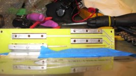
Well another day sweating bullets. I found out my las cell was inserted backwards so I had to take it out and redo it. Yuck I hate that. I saw a teeny but of smoke coming out of the board an behold a trace had vaporized. I guess I can replace it with some small wire soldered in unless someone else has a brilliant idea. Quitting time for today. I will definitely use the smallest insulated wire I have and perhpas glue it down sinc once I put the next cell in i will not be able to reach it.IMG_0359.JPG Any expert suggestions are appreciated.
otherDoc
 
How did you managed to burn the trace?! Is it complicated to assemble? I thougth it was quiet easy or is is just me? U can run small wire and then just glue it to the board, no problem there. the markings on the cell has to face one another. Top and bottom cells has to be blank on the outside.
 
I did manage to solder the wire in. The trace I think just lifted and contacted the wrong pole. Smoke and a little zap. I used some hot glue as stress relief on the solder joints but I think I am going to put some varnish on the remaining traces just in case. Cells are oriented correctly but your reminder about blank face on both end cells is a great way to remember it.IMG_0360.JPG It ain't pretty but it does have contiuuity.
otherDoc

I'm old and I shake a bit, so it is not as easy as it seems. The thing is every zap really is a big one and on the video they look a lot less scary than in person. I am getting better as I go, but there are some places thaat I have made mistakes and had to do stuff over. It definitley slows down progress. I wish there was a coating for the tabs that could be removed after they were put in. It would make assembly less intimidating. I'm using the tabs full length and have lots of tape between them. I may take a hint from Ping and use weather stripping when it is finished with silicone paper between the cells.
 
Eureka! I think I found the answer. Clothes pins are great non-metalic clamps to hold the blocks in place. Will demonstrate tomorrow if it works!
otherDoc
 
I think ping puts the window foam inbetween so as to line every thing up maybe drop the borad on all at once.I was going to use it. And is a perfect fit. But the durlenght build was strong. Till I didn't like one alumiun buss block and changed it Damm nabit a liitle flash of a small corner of a tab. thought i could slide the third one out easy but. Doc could you tape the taps all together then drop the board on all at once with the tabs taped and do one at a time scewing one down at a time. lots of tabs up in the air. maybe not. I used wooden clothes pins the hold 6 cells together for parelle charge, love wood and plastic.
 
The slots are pretty narrow and precise so even dropping in one cell with the holes punched is tricky. I will tape the lower 2/3 of the tabs so that they are shielded. I think it is better to not shorten the tabs if for no other reason that if you mess up one with hole punching you have plenty of room to cut off the bad part and try again.
otherDoc
 
Now they're all coming together anyone want end plates? Got 30 pairs. PM's best.
3mm solid phenol. Plain phenol finish business side, white finish outer side.
Dimensions best look at photos.
This material is very hard and light and hard to bend. Won't burn or melt. Electrical Insulator.

20120720_082624.jpg
20120720_082735.jpg
The partially completed pack put together http://www.endless-sphere.com/forums/download/file.php?id=78240&mode=view
Held together with a lightweight steel frame i can spot weld it now I've made the spot welder.
I was pulling around 400A from an A123 cell, spot welding other day and couldn't touch the copper bus on the tabs, would have removed my finger prints.
Any flammable material near the tabs probably would have burnt, a slighly loose higher resistance connection if it burns away in a battery box shrink wrap and wood being the materials of choice hmmm.
 
One 6 cell finished and one more to go. There is definitely a learning curve to doing these but I did learn some things.
1. Button head bolts suck and strip too easily. I'm going with all allen heads for the nest build. Much easier to handle for old fingers.
2. Tape the batteries off at the top just leaving the tab and holes exposed. Tape everything you can see during assembly.
3. This is slow work unless you are young and agile of hand. I used to be a surgeon but now at 67 I don't have the deftness that I used to.
4. Now I must test this battery. I gotta make up a harnass for the Hyperion and attach the main leads to the brass bolts.
IMG_0363.JPG

Stay tunes 'cause if I can do this you can do this. Very fine design to the kit shows through all my mistakes but hopefully battery 2 will go a bit easier.
 
docnjoj said:
1. Button head bolts suck and strip too easily. I'm going with all allen heads for the nest build. Much easier to handle for old fingers.

Some heads are deep enough to stay on the allen wrench to insert horizontally & not easily fall off. Is there enough room to insert level & avoid angular shorts?

Also, what about using a sticky substance to keep the button head attached to a hand tool & screw-in by hand or press-in with "spring loaded" turning to avoid using "the stripper" electric tool??? :idea:

Consider putting insulating tape around the tool "rod" to prevent angular shorts too. ;)

I will tape the lower 2/3 of the tabs so that they are shielded.

What would be the best tape options to use? Also, what about putting some dense foam spacer between the tabs to prevent contact or rubbing? I guess that's what Ping does with the "window insulating foam" strip idea?
 
docnjoj said:
One 6 cell finished and one more to go. There is definitely a learning curve to doing these but I did learn some things.
1. Button head bolts suck and strip too easily. I'm going with all allen heads for the nest build. Much easier to handle for old fingers.
2. Tape the batteries off at the top just leaving the tab and holes exposed. Tape everything you can see during assembly.
3. This is slow work unless you are young and agile of hand. I used to be a surgeon but now at 67 I don't have the deftness that I used to.
4. Now I must test this battery. I gotta make up a harnass for the Hyperion and attach the main leads to the brass bolts.


Stay tunes 'cause if I can do this you can do this. Very fine design to the kit shows through all my mistakes but hopefully battery 2 will go a bit easier.

There is a mistake in assembly. You need to turn end blocks. It has to be level on the edge with pcb. Take cover plate and place it over to see what i mean. Good to hear someone almost finished a batt.

Button bolts should be good enough, do not overtighten them cause aluminum is softer to prevent damage to the threads.

deVries, use any insutation and i recomend to use it on front blocks meaning ataching a block at a time and then masking it. shorts happen when you puy one bold and by accident drop the block. Tape will prevent this.
 
ohzee said:
Yea I tend to agree I am also a bit hesitant to cut my tabs for a few different reasons.

I have all my cells cycled, charged and balanced. Still waiting on my BMS , but figure I will start putting my pack together.

Hey, what's your status? When are you doing your battery assembly? We can't be patient for much longer. :razz: My cells ship next week! I want you to go 1st. :lol:
 
There is a mistake in assembly. You need to turn end blocks. It has to be level on the edge with pcb. Take cover plate and place it over to see what i mean. Good to hear someone almost finished a batt.

Button bolts should be good enough, do not overtighten them cause aluminum is softer to prevent damage to the threads.

deVries, use any insutation and i recomend to use it on front blocks meaning ataching a block at a time and then masking it. shorts happen when you puy one bold and by accident drop the block. Tape will prevent this.

Thanks! I wasn't sure but it certainly makes sense that the end blocks go inside. I'll fix it! At least those are on the outsides! I do think that I am going to use socket heads instead of the button heads. They do allow for horizontal assembly easier. The stainless little bolts strip out much more easily than the blocks in my opinion. Then they are a nuisance to get out. One even had its head strip off. I used a locking long pointed vice-gtip and got it.
DeVries
You can use the supplied button heads horizontally but socket screws stay on the driver better. I use a wooden clamp like for woodworking to support the cells vertically and the one being worked on like a tent. You could use super glue to keep the screws stuck to the tool if working vertically. I use blue painters tap around the top and tabs of the cell and it minimized shorts.
otherDoc
 
There that's better!
IMG_0366.JPGIMG_0365.JPG
Definitely looks neater this way! Also the slightly larger sockets are easier to handle. It is my lot in life to make the mistakes so you guys don't have to :oops:
otherDoc
 
Doc I'm on you side. I got my battery togethere and two test runs but not boxed yet or enclosure, just tupperware and a bingle. They all keep balance well. Good sign.
 
I believe what happened is that I rotated the alloy block and caused a dead short when I did that. Afterward I soldered a wire in to rebuild the trace. Then I started covering everyting but the part I was working on with blue tape and had no more problems with the assembly. I'm afraid I had a learning curve that I fell behind on. Agnius makes it look easy but he is an expert with this kit, I'm so much better than when I started but still am learning. The first battery (6S) is this one and is fully assembled and ready to charge. Pictures at the end of the day after I solder up the harnass and the main connections to go to the Hyperion.
otherDoc
 
1) Can you describe in more detail how far down the tab you center your hole to hole-punch? Did you make a jig?

2) Do you bend the tab by hand after inserting through the slot?

3) Is the hole punch from Amazon working well giving clean level cuts? Single hole punch one at a time? What is the hole diameter vs pcb holes?

4) Are you using the silicon paper between cells that is used for baking?
 
If deVries would copy my PM it will answer all those questions. Meanwhile back at the sweat shop
Thsose connectors are really tough to attach to the board pins. I had to open the female ones while they were inserted with a tiny screwdriver and finally managed to press the male and female parts together. This is with fairly precise soldering and heat shrink on the wires. I don't think these can come apart many times without damage.
They may be better than Jhs- XT connectors but they are quite difficult to assemble and even more difficult to connect. I used the conductive grease an it helped to seat the female connectors.
But one battery is done and will test tomorrow.
otherDoc
P.S. Definitely check your connection locations because those things are also hard (impossible?) to get out of their sockets when fully seated. You really don't want to make a mistake here! Perhaps there is a specific crimper that would make perfect crimps but I was able to use a hemostat to do a reasomable job
 
deVries said:
1) Can you describe in more detail how far down the tab you center your hole to hole-punch? Did you make a jig?

2) Do you bend the tab by hand after inserting through the slot?

3) Is the hole punch from Amazon working well giving clean level cuts? Single hole punch one at a time? What is the hole diameter vs pcb holes?

4) Are you using the silicon paper between cells that is used for baking?

Docnjoj replied...

1. I use the alloy block and use a scratch awl on some wood to first locate the hole, basically centered left to right and at the edge of the tab. If yo make extra on the tab it ownt fold flat and id a real nuisance to get the holes alligned with the next cell.
After the holes are through I use the 1/8 punch to make the correct size holes.
2. Yes but I burnish the layers with a metal tool like a knife handle.
3. Yes
4. Yes but after I test the battery before I put a case around it. I'm still probably going to use perferoated hardboard 1/8"
 
Thanks deVries! I'm too tuckered out from my fight with the connectors to do any more tonite. I would like to get good at making those things but I think it is easier to solder the wires permanently to the battery and use the Hyperion connectors to hook up at the other end. I still need the JST-XH ones at the far end to use the Hyperion and celllogs. The euro ones are different spacing and heavier.
otherDoc
The perforated hardboard will just be for the 2 end compression panels and it wil probably be held together in compression with zip ties at the edge holes. This also makes it easy to disassemble if I need to replace a cell. i think the ideal separator is Formica or laminate as it is fire resistant an fairly strong. My parchament paper is fire resistant but not strong.
 
has anyone got a hold of the tinning flux for the aluminium tabs as yet, it was discussed about a month ago on one of the a123 20ah threads, cant find exact
thread, the discussion started from a youtube vid showing a guy tinning the alum. tabs.
ps nice work docnjoj
 
Agniusm deserves most of the credit for designing and manufacturing the kit. I still think it is the most effective way to assemble A123 20 ah cells.. I am old an complain a lot but this is a superior method to build this battery. I still havem't found a good way to solder these tabs, so compression is the best way with blocks and bolts.
otherDoc
 
Hi, what is the problem with the connectors? I have just done mine for iCharger and it was easy as 1,2,3. Pins can be reused many times if u solder not crimp them and they are easy to take out by presing and releasing pin to slide out. Bare in mind that i was building battery on the video first time. Prob i will have to make vid on soldering pins etc.
Regards
 
agniusm said:
Hi, what is the problem with the connectors? I have just done mine for iCharger and it was easy as 1,2,3. Pins can be reused many times if u solder not crimp them and they are easy to take out by presing and releasing pin to slide out. Bare in mind that i was building battery on the video first time. Prob i will have to make vid on soldering pins etc.
Regards
I think my crimps plus shrink tubing were too thick for the back end. I'm just going to leave it connected and do the second connector with no crimp as you suggest. I will use hot glue to replace the shrink tubing and we shall see what happens. If it fails again I think I will just solder the wires to the pins thenselves.
otherDoc
 
Back
Top