Migration from Lipo to A123 Lifepo4 battery pack

danoussh

10 mW
Joined
Aug 20, 2013
Messages
23
Location
France
Hello fellow members of Endless-sphere,

I'm seeking guidance to help me make my own A123 LifePo4 split battery pack.

Until now my setup was this:

  • - Bike - Rockrider 6.3 2013 – Decathlon http://www.decathlon.fr/rockrider-63-id_8103
    - Magic Pie 3 26” motor, removed internal controller, replaced phase wires with 2.5mm copper wire, added temp sensor for later.
    - 12 FET 3077 Mark II Extreme Modder LYEN Edition Controller Motor 40A.
    - 6 x 6 cell Turnigy 5000mAh / 20-30 c discharge LIPO – 3bats in series and then paralleled with another 3 in series = 10ah 72Volt. No BMS!!! <--- BAD :oops:

View attachment 2


My range was about 15-20Km with some light pedalling. I would like to add more range and more security and why not some lifespan.
This seems to all come to using LifePo4 A123 prismatic AMP20M1HD-A battery cells.

It seems hard to find genuine cells. Cell_Man seems to be the man. I'm not sure about OSN?
So where to buy? What's the price? :?:


My goal is also to make a 24s split battery pack.


How I would like to do it:

For the battery pack, I need to find the best place for the battery cells on my bike for an appropriate balance between the front and rear. I would like more weight at front of the bike for better control and front tire traction. I also changed my front suspension with a ROCKSHOX suspension RECON Silver TK Coil 100 mm Noir 2013. This has made the bicycle tire traction way better and reduced handlebar vibrations. But it’s still a little light at the front of the bike. I want to keep the bike as off road as possible.


But I also need range, so I’m looking into A123 prismatic cells from Cell_Man to create a homemade 24s split battery pack. I want to place 12 cells on each side of the bike, to make a 24s battery pack with BMS.

Here is a picture found on endless-sphere which illustrates pretty much how to connect the battery together. I would like to place on each side of the bike; 2 separate 6s battery packs, which will be set head to head like this picture. The reason I want to use head to head is to reduce as possible wire length and keep vulnerable parts together and not space out. To attach the cells, I’ll use Agniusm’s A123 AMP20M1HD-A Battery pack 6S kit. Then I still need to find a way to keep the cells head to head. In this picture it doesn’t seem have much as structural strength if I were to place this on the side of the bike between my legs. My goal isn’t to reproduce exactly this idea, but to evolve this idea towards my project.

Keep in mind, I going to build it to be able to dismantle it if any problems arise.
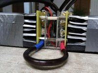
a123_pack_12s-2x6s_IMG_20120208_200008 (Medium).jpg
Fig A; 12s --> 2 x 6 cells head to head.


This sketch will help you imagine my idea.
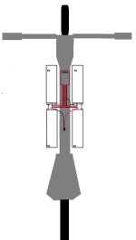
schematics_1 (Medium).jpg


How is a BMS connected to the battery pack, controller, and charger?

Here is a picture supplied by Em3ev for a 24S 80A BMS.
It says to connect each negative wire to the bms. This leaves us with a positive wire for the controller, charger and battery pack. Does this mean all these positive wires are connected together?
So if I’m not mistaken, I need to choose appropriate controller to accept charging voltage.

When I charge the battery pack, will the controller be on/powered up?
Does the controller ignition wire need to be connected to the BMS? Or could just leave it connected the positive wire with a switch in between.
Does Cycle Analyste power up and show battery/charger voltage?

View attachment 3


What do you guys and girls think of all this?? What am i missing?

Any ideas? Feel free to post info, links suggestions.

Best regards,
Danoussh
 
As far as I know
here is one of very few authorized A123 suppliers:
http://www.buya123batteries.com/
They do not sell QC rejects like Victpower for bargain prices like $24.
Mavizen is UK authorized supplier for A123.
They had been charging $70 for A123 20Ah pouch for years.
Mavizen quoted me $70 for the pouch almost 3 years ago.
As far as I can say there is nobody on this ES forum who bought from them and reported here.
 
the red wire never goes to the BMS unless you have a really cheap BMS and they are skimping on the top wire.

you do not have to put the BMS up on the top tube, it can be remoted to the place where you put the controller, and then run the B- wire from the battery to the BMS. put your wattmeter shunt wire, the black wire,in that B- wire to the BMS. you can take the voltage to the wattmeter on a small wire and bypass the red wire in the wattmeter (you can open the wattmeter and take the shunt out and remote it if you wish and you can remove the two large red wires in the wattmeter and use a small wire to carry the pack voltage to the spot in the wattmeter where the red wire soldered in). take the voltage from top of #12 since 24S is too much for a 60V wattmeter so you have to mentally double it. also it is possible it appears to use regular 12-10G wire as the shunt so you could use that for the shunt of the wattmeter and have the wattmeter out on the dashboard with the kelvin leads to the watt meter from that wire shunt.

you would have to extend the BMS sense wires if you do that and have your 4x6S packs hanging off the top tube like that. maybe you can mount some of them in front of the head tube like oatnet did.

you can use any sequence you need in order to make the pack fit where you have space. 8S+8S+8S or 5S+7S+12S, anything is ok but you need a big big wire to connect the sections, use 10AWG-(8AWG for connections longer than 12" IMO).

you also have to put the sense wire in the middle of that connector between sections. there is a voltage drop on each of the connections between sections that is larger than the voltage drop in the short sections in each of the packs.

so you put the sense wire in the middle of the big wire you use to connect them so you are able to split the extra voltage drop between the two cells on each side of that connector to reduce the effect when you get close to the LVC during sag under load.

make sense?
 
I run two 12S A123 20Ah packs on different bicycles.
Both packs do not use any BMS, only cellogs during charging .
My cells are never top balanced, they bottom balance themselves beautifully after just 1Ah used into the ride.
After charging terminated on first buzzer from celllogs /3.6V reached on whatever cell/ 12 cells voltages range from 3.49V to 3.65V .
1-2 km into the ride all cells bottom balance themselves to 3.3V. At this point you can say they all 12 cells are at the same "starting point" when they ready to deliver at minimum 15Ah "in unison" .
 
With lifepo4, balance at working voltage means nothing. They're at 3.3V when nearly full, and also when they are nearly empty. If you believe that they balance themselves then you're mistaken. It only means they are at their working voltage. One cell could be almost full and another almost empty and show about the same voltage. That's why they balance them to 3.6V. Now if you charged them all to 3.6V, you effectively did balance them, but looking at a bunch of cells at 3.3V tells you nothing. One could have 18ah left in it and another could have half that left in it. The voltage curve on lifepo4 very flat compared to LCO or other lithium chemistries.
 
18s lco is 66.6V, not 72V. and as long as you balance charge, there's really no need for a bms. You'll need at least 21s in lifepo4 to match 18s lco.
 
so according to you LiFePo cell 18Ah discharged can be at the same voltage at LifEPO cell 9Ah discharged.
10 seconds after removing load cell discharged 18Ah is at the same voltage as cell discharged 9Ah.
Discharge curve shows me something else and I seen tens of them on my CBA.
Discharge curve is NOT flat even for LiFePo.
 
he is talking about resting voltage and is totally right. if you do not compensate for self discharge by balancing the battery to full charge on a regular basis you have no idea how much charge is left in the cells or if it is even close to balanced. even if they are A123. they start leaking as they age, and some a lot more than others. i would say you are getting by on luck and the high quality of the A123 cells. but for regular store bot chinese ping pack lifepo4 they change with age.
 
what do you call "resting voltage"
Maybe on your A123 battery.
No way 18Ah discharged cell will have same voltage as 9aH discharged cell. those cells are good but not THAT good.
Discharge curve is everything and it does sags with discharge.
I am not paranoid how many Ahs I have left, plenty for my rides anyway.
Celllogs provide protection during charging /never above 3.65V/ and during discharging /never below 2.8V/ on my bikes , that is what I am getting by, what luck you are talking about?
What "leak" you are talking about,
over 300 charge/discharge on CA , they are happy.
Balancing is based on what, what we call balanced , voltage not important?
 
you really should not be giving other people, especially newbies who don't know anything about batteries, advice about how to assemble a battery pack. there are people who will believe what you say and then they are stuck with misinformation as the basis for their own knowledge of batteries.

you can do what ever you wish, but don't tell these people they can 'bottom balance' as though it is a realistic way to manage their batteries. if you don't understand resting voltage or self discharge, there is nothing that can be done to overcome that.
 
For everyones benefit, resting voltage is the stabilized voltage of a battery that has not been under load for a period of time for the voltage to become stable. It has nothing to do with the state of charge (SOC) of the battery. Lifepo4's discharge curve is so flat, it's impossible to tell the soc of the cell unless it's fully charged, or almost fully drained. 90% of it capacity is between 3.2V and 3.3V, where with rc lipo for instance that would be 3.5V and 4.2V on a somewhat even curve.
 
I tend to agree, lifepo4 will be much harder to manage with no bms than lico. But I think you could manually top balance if you wanted to, by charging to 3.65v per cell minimum. Then treated nice, you could go a long time with no large imbalance if the cells are all good cells.

But personally, I'd find that much battery straddling the top tube a real pain to pedal around. Ok, no pedal. I have built bikes like that too, but I left a bit of room to stand over the bike near the seat.

72v of A123's, I'd want a real cargo carrying bike to pack that much bulky lifepo4.
 
I do not give any "advice" as you write.
I am writing about my experience and how I do things just like everybody on this forum.
Nothing wrong about it.
If you disagree with my way of doing thing that is your right.
Newbes as you call them should read through tens of posts on subject and form opinion/decide and this is what they do !!
My first A 123 20Ah pack is at 365 cycles right now and doing great with no sign of deterioration.
I am not the first and not only one who NOT balance cells at the top.
I can provide reference here if you wish.
I know my stuff and I am confident my cells love it this way.
 
I would not repeat his explaination but what he writes here makes sense, do you see his point?

http://evtv.me/2009/11/get-rid-of-those-shunt-balancing-circuits/
 
that guy is an ignorant fool. his advice is worth nothing. it is misleading and is totally ignorant of how lithium ion storage works. that has been made clear for years. that's why he calls this place endless-fear because it was made clear here that he is a fool for thinking up this idea of bottom balancing.
 
RE the link;
He writes a convincing argument, but which ever way a pack is managed its capacity is governed by its weakest cell, top balance and monitoring the pack discharge with a BMS will cut it off when the lowest capacity cell is empty preventing cell death. The method described in the link will extract the same capacity and it could be argued that there is less chance of over discharging with bottom balance but he is over charging the lower capacity weaker cells which will shorten their life and capacity compounding the problem.
To kill cells he must have been using overall pack voltage for his low voltage cut off, the reason he killed them was not leaving a safety margin or having built a pack from mismatched cells.

Reading that did make me think about balancing my lipo pack at 3.65v with a life bms, then bulk charging to full capacity and measuring all the cell voltages, some useful information about your pack may be gained this way?
 
Top balancing or bottom balancing , electronics should perform LVCut off, they "should".
Read through posts on this ES forums and you can read and read about faulty BMSes all over the place.
Bad soldering, shoddy traces, failing components and list of BMSs failures goes on and on.
Again in my book for A123 all you need is 2.8V LVCut off and 3.65V HVCut off for charging.
Maybe I sacrifice a bit capacity but I still have plenty even at 15Ah.
If it comes to "overcharging weakest cells" as you put it ,
AGAIN
I have HVC during charging of course perform by celllogs
I doubt with his system he would not have HVC of 3.6V, how do you presume he overcharging weakest cells?
All I want is NOT to trust my cells to shoddy BMS electronics, I do not want to take a chances.
But it is only me.
Go ahead and use ones at your risk.
Why would I need complexity of BMS if I can do without them?
Celllogs are simple and effective for my packs
What Jack writes makes a sense , but it was foolish that he did not have cell levels LVC on those ecars and allowed for cell destruction.
IMPORTANT
I do not use Jack Rickart advice, I found out about him long AFTER I started using my A123 pouches with no BMS electronics connected.
 
no, what he says does not makes sense. if he knew anything at all he would not even write the stuff he does. he is a tv personality with a brain of a worm.

but you should not be telling people to build batteries without using a BMS and telling them to instead use some hair brained scheme you imagine may work.

it is immoral to deliberately misinform people who don't realize you do not know what you are talking about.
 
Miro, this is a quote from that link, I didn't presume anything.

--------------------

The solution appears to be BOTTOM balancing. With all the cells discharged, I replaced the dead one, and balanced all the cells at 2.90 vdc. Then recharged the pack to 87 vdc (3.625 vdc per cell).

Now the cells are very unbalanced at the top – some slightly over 4 volts and some quite under the 3.625 average.

--------------------

Now I don't call that a solution?


It will be the lower capacity cells that have gone above 4v because his bulk charging has put equal capacity into each cell, the over charging will damage those cells further reducing their capacity further so next charge they go even higher etc.

While I agree a BMS is not a fit and forget item particularly in a multi cell paralleled pack where an individual cell could be lost and the remaining string mask that from the BMS and user until they die from being over worked but they still have benefits above using none at all. On large capacity single cell packs, eg 20s1p, a good BMS is in its element as it can control all the cells correctly and accurately and will let you know as soon as it fails to perform as it should. A lot of the pack problems we have seen fitted with a BMS are multi paralleled packs or have suffered because of user connection errors, connection failures or wire failures, or users failing to understand the charge procedure and stopping it before balancing is accomplished. Of course I accept there will be BMS failures too, anything can give up due a to QC of components etc. Some of the problem of using a BMS is people stop any manual monitoring and totally hand over control of the pack to the BMS, this is fine in a single cell construction but not with multiple cells in parallel strings.
 
of course if he bulk charged with no HVC he might overcharge weakest cell, but I doubt it , he never says he does not use 3.6V cut off.
He charged to 87V and with his all equipment he would not have 3.6V cut off? I think he uses 3.6V cut off just don't mention it.
For sure he does not use LVC.
but it is just on the side and not topic of this discussion.
I am discussing here no need for BMSes on LIFePo chemistry.
the moment my first cell reaches 3.65V charger is cut off.
ALL 12cells /not balanced at charging/ arrive to exact same voltage /within 10mV/ after just minutes of riding /applying 10-15A load to them/.
Farther into ride individual cell voltages drop uniformly , even after 15Ah used they all stay at 3.28- 3.29V.
Arriving home hour after the ride 12 cells all stay at same voltages /within 10mV/.
Again this are A123 20 Ah pouches.
That what I wrote above is NOT my opinions, they are facts.
I am sure they will work like that for a long time.
 
Back
Top