JeremyBP
100 µW
Hi all,
This is my first post here, so please pardon me if I'm putting this in the wrong place.
I build tiny electric vehicles (go-kart like things, pocket bikes, scooters, etc). One of the events I regularly participate in features an endurance race, during which I have to change my batteries several times. So I decided I wanted a quick-change battery system. This thread will chronicle my attempt to build one. Please, if you have any thoughts or feedback, jump right in. I'm not exactly an expert at this.

I'm starting with these. They're surplus A123 prototype modules that were once used for starting jet engines. They're 26.4v nominal, with a built-in BMS and all the associated niceties. Each one of my battery modules is going to have two of these in parallel.

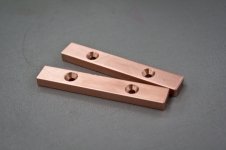
I made some copper bus bars to attach them. They might be excessive, but if this whole thing works out, I'd like to keep using them for various projects in the future, and I want them to last. So big copper bus bars it is.

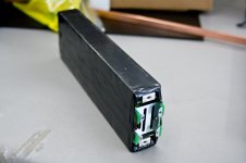
And then I put the whole thing in a box. This is my module. I want to cut a keyway in one side, and key the slot it will slide into so it's impossible to put it in backwards.
What I envision for the receiver is a box with terminals at one end that I can just slide a battery module into and latch it in place. Then I want to change batteries, I can just slide out the old one, and slide in the new one. Which brings me to my question. What do I want to do for terminals in the receiver? I was thinking more copper bars (with beefy wires coming off the ends) mounted on springs, but I'm not sure. I'd love to get some ideas and feedback from you guys.
Cheers,
Jeremy
This is my first post here, so please pardon me if I'm putting this in the wrong place.
I build tiny electric vehicles (go-kart like things, pocket bikes, scooters, etc). One of the events I regularly participate in features an endurance race, during which I have to change my batteries several times. So I decided I wanted a quick-change battery system. This thread will chronicle my attempt to build one. Please, if you have any thoughts or feedback, jump right in. I'm not exactly an expert at this.

I'm starting with these. They're surplus A123 prototype modules that were once used for starting jet engines. They're 26.4v nominal, with a built-in BMS and all the associated niceties. Each one of my battery modules is going to have two of these in parallel.

I made some copper bus bars to attach them. They might be excessive, but if this whole thing works out, I'd like to keep using them for various projects in the future, and I want them to last. So big copper bus bars it is.

And then I put the whole thing in a box. This is my module. I want to cut a keyway in one side, and key the slot it will slide into so it's impossible to put it in backwards.
What I envision for the receiver is a box with terminals at one end that I can just slide a battery module into and latch it in place. Then I want to change batteries, I can just slide out the old one, and slide in the new one. Which brings me to my question. What do I want to do for terminals in the receiver? I was thinking more copper bars (with beefy wires coming off the ends) mounted on springs, but I'm not sure. I'd love to get some ideas and feedback from you guys.
Cheers,
Jeremy

