Hey Dudes,
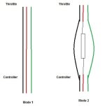
I want to add a simple remote (one from eBay) that will switch between regular throttle mode (all connected normal) to red wire with resistor through it like so:

* The whole thing will be mounted inside the controller
I have this remote:
http://www.ebay.com/itm/152204177998?_trksid=p2057872.m2749.l2649&ssPageName=STRK:MEBIDX:IT
I have two problems, one is that the thing requires 12v input and I want to avoid adding a step down converter and the second problem is having the relay switch between two modes and not just open and close the connections in a single wire.
About the 12v voltage input for the remote switch, I was told by someone in this board that I can use a simple AC adapter that receives 110v/220v from the wall and drops the voltage to 12v DC as a step down converter for my 88v battery pack (88v DC doing into the 110v/220v side) and that it works great.
I noticed this thing on eBay:
http://www.ebay.com/itm/AC-220v-10A...587647?hash=item3388fc98bf:g:V9UAAOSwrklVGU9J
But it seems that when the circuit is closed then it takes the whole 88v (in my case) into the load which is something I'm not looking for.
What do you guys thing?
This whole thing got me so confused I need to go eat and rest a bit to clear my mind...
I want to add a simple remote (one from eBay) that will switch between regular throttle mode (all connected normal) to red wire with resistor through it like so:

* The whole thing will be mounted inside the controller
I have this remote:
http://www.ebay.com/itm/152204177998?_trksid=p2057872.m2749.l2649&ssPageName=STRK:MEBIDX:IT
I have two problems, one is that the thing requires 12v input and I want to avoid adding a step down converter and the second problem is having the relay switch between two modes and not just open and close the connections in a single wire.
About the 12v voltage input for the remote switch, I was told by someone in this board that I can use a simple AC adapter that receives 110v/220v from the wall and drops the voltage to 12v DC as a step down converter for my 88v battery pack (88v DC doing into the 110v/220v side) and that it works great.
I noticed this thing on eBay:
http://www.ebay.com/itm/AC-220v-10A...587647?hash=item3388fc98bf:g:V9UAAOSwrklVGU9J
But it seems that when the circuit is closed then it takes the whole 88v (in my case) into the load which is something I'm not looking for.
What do you guys thing?
This whole thing got me so confused I need to go eat and rest a bit to clear my mind...


