FOC Help Needed

Breville

10 mW
Joined
Jun 1, 2022
Messages
28
Location
The Southwest
Hi everyone--longtime lurker, first time poster. I eventually want to create my own motor controller for an eBike, but have decided to start out learning the fundamentals of motor control using a development board and a motor controller add-on board, in this case an ST Nucleo-F401RE and X-NUCLEO-IHM07M1 combination. I chose these because they were available and because I'm already very familiar with STM32 from other, non-motor control related projects (I mostly use high-end STM32F7 and STM32H7 parts for those applications). I also have a small PMSM motor to use in this project. It's only 15 watts, but I figure with a motor this small I'm not likely to blow up the output MOSFETs on my board. I have the whole thing powered by a lab power supply and have the current limit set to prevent catastrophes. Yes, I know I can buy a motor controller, but I'm doing this as a learning experience.

My first project was to get this motor working in six-step mode. The motor has both Hall sensors and a 1000 count per revolution incremental quadrature encoder with index. This part went really well and I can spin the motor in both directions, ramp the RPMs up and down, and control the whole thing with PID.

My next step was to implement full-blown FOC. I read up on this and have succeeded in getting basic FOC to work with all of the basics (Clarke/Park transforms, space vector PWM, etc.) At this point, I'm running the motor by manually controlling Iq and Id -- I don't have them under PID control yet due to my first issue--current measurement.

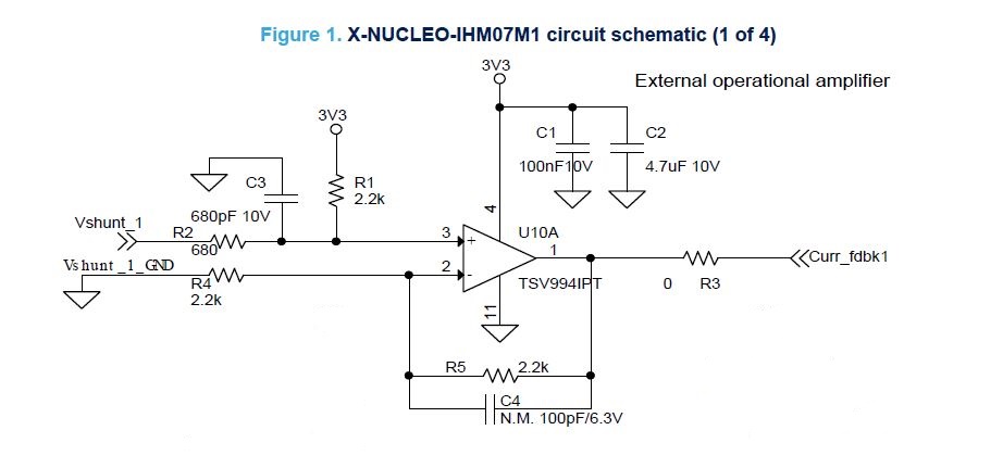
The IHM07M1 board has shunt resistors on the low-side of the three output MOSFETs and there are opamps on the board to amplify the voltage drops across the shunts. I'm not an electrical engineer, so I think my first problem is that I'm not using the right gain for the opamps. I say this because when I read the shunt voltages and calculate the currents, they add up to about double what the power supply is showing for the entire board. Here's a diagram of one of the opamps (the other two are the same):
opamp1.jpg


Based on my limited understanding of opamps, I came up with this for the input and output voltages:

Vout = m*Vin + b

where:
m = (R1/(R1+R2))*(1 + R5/R4)
b = Vref * (R2/(R1+R2)) * (1 + R5/R4)

So with the resistor values shown in the schematic, I get:

Vout = 1.5278Vi + 1.5583

Vin = (Vout - 1.5583)/1.5278

Another question: When to measure motor phase currents? Since the shunt resistors are between the low-side MOSFETs and ground, I assume I want to measure current when the low-side MOSFETS are on and the high-sides are off? Is this correct? Right now I'm measuring them at the beginning of a PWM cycle during the t0 time when all three low-side MOSFETs are on. Unfortunately, the STM32F401 only has one ADC, so I'm reading the three phases sequentially.

The current measures seem to have several problems. In addition to adding up to more than the total power output by the power supply, they're very noisy. I mean really noisy! Some of this may be due to my tiny motor drawing very little current (about 75 mA at 1000 RPM) so that it's spanning only a small part of the ADC's input range. I can filter it to make it less noisy, but I'm concerned that this will introduce lag that will affect the FOC calculations.

Another issue with the phase current measurements is that when I use the full form of the Clarke transform (Iαβ0), the "0" term is non-zero most of the time. Since this is a balanced system and the phase currents should sum to zero, I'd expect I0 to be zero (at least most of the time anyway). Is this more likely due to the noise in my current measurements, or an issue with how I'm measuring and calculating the currents?

Another issue I'm having is motor direction. I can only get the motor to spin in one direction. For an FOC implementation using SVPWM, how do I get it to spin the other way? I know this probably should be obvious, but I can't figure it out.

Yet another issue is finding the motor's magnet poles to set the initial angle at startup. Is there a preferred way to do this? At the moment I'm energizing the U-phase high-side MOSFET and the V and W low-side MOSFETs, waiting for the rotor to settle down, and then zeroing the encoder's position. This seems to work much of the time, but sometimes the motor doesn't start spinning--it just gives a little jerk and stops.

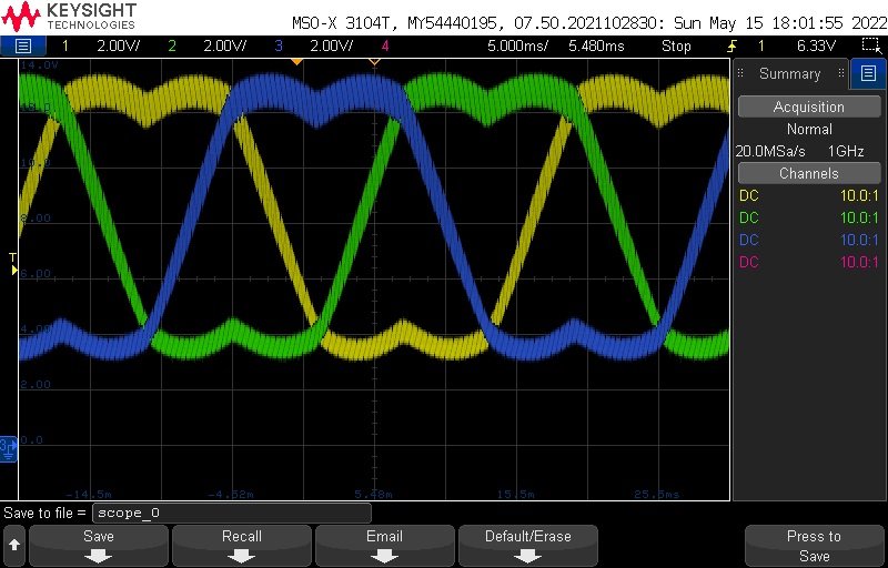
Lastly, when I look at the controller's output waveforms on a scope, they look nice and pretty, just like in a textbook, but they always seem to have an 8V DC offset. My power supply maxes out at 16V, so the DC offset of the waveforms seems to sit at exactly half of that. I can vary the peak-to-peak height of the waveforms, but they are always centered at 8V. Is this normal with SVPWM? Will it affect the motor, perhaps making it less efficient? If it's not normal, how do I fix it?
scope-0.png


Any help/advice would be greatly appreciated! Sorry for the long, rambling post.
 
Breville said:
The IHM07M1 board has shunt resistors on the low-side of the three output MOSFETs and there are opamps on the board to amplify the voltage drops across the shunts. I'm not an electrical engineer, so I think my first problem is that I'm not using the right gain for the opamps. I say this because when I read the shunt voltages and calculate the currents, they add up to about double what the power supply is showing for the entire board.

If the op-amp gain is not adjustable (etiher in hardware or software) you can determine the gain by checking what resistors are used in the op-amp circuit (and what specific circuit is used); there are some good electronics-teaching sites that show how they work and what math is involved, like here:
https://www.allaboutcircuits.com/textbook/semiconductors/chpt-8/introduction-operational-amplifiers/
so you can look at the op-amp schematic of the dev board you're using (usually available on the website for it if it didn't come in hardcopy with it), and match that to one of the types of op-amp circuit on that site, and use the math for that type to calculate it's gain. Then you'll know for sure what gain it's using, and what scale signal it is putting out.

Then if you like you can do a test using a known constant current (from your lab supply, for instance) thru the shunt on the op-amp (without a motor connected and without the motor control software running), and see what reading the op-amp gives for that current, to verify the gain calculated is accurate.


Phase currents can easily be higher than battery current, because battery current is more or less continuous, but phase currents are pulsed via PWM, and are also cycled thru the rotation of the rotor, so they are much higher during the highest part of the load on a phase, lowering to far less than the battery current at minimum load. The switching of these currents is also going to induce some noise into any signal you read from them.

Some FOC controllers (like Incememed's SFOC5) use an "audio signal" into the phase signals to determine rotor position; this signal is present at all times whether the rotor is in motion or not, for the SFOC5, and for me was very annoying. I understand that it does not have to be audible, from comments from various people when this comes up.

Some like Lebowski's use hall signals for zero to low speed operation then switches to sensorless when sufficient RPM for easy rotor position reading.


I don't know enough about FOC math to help with the measurement details, but there are a number of FOC motor controller design threads around here, some from scratch, some based on VESC, etc. Some have their hardware and code published here (or elsewhere like github) as well, such as the Lebowksi brain, if that's helpful. There are often screenshots of 'scope measurements as well, along with discussions of powerstage design, etc (which may include how and where / when to measure currents, and how to work around the noise).
 
Thanks for the reply, amberwolf. :thumb:

The part of the opamp circuit that’s confusing to me is the 3.3v bias added to make sure the input is always above 0V, since with FOC phase currents can be negative. Otherwise, this is a simple non-inverting amplifier. I’m about 70% sure I did the analysis correctly, but a check from someone with more experience with opamp circuits would help (I’m a firmware guy, not a hardware designer).

I like your idea to inject a known current into the shunt and measure the output of the opamp—I’ll see if I can set this up.

Regarding rotor position, I have it easy here as my motors all have quadrature encoders. If I ever do tackle sensorless, it’ll be after I get it working solidly with the encoders (why make it harder than it has to be, right?)
 
I've used this paper from ST for developing my own firmware:
https://www.st.com/content/ccc/resource/technical/document/user_manual/5e/5e/d2/cb/07/35/45/a6/CD00298474.pdf/files/CD00298474.pdf/jcr:content/translations/en.CD00298474.pdf

Especially the timing for the phase current measurement is quite tricky.
Do you use the ST Motor Control Workbench?

regards
stancecoke
 
Hi and welcome to the painful world of motor control! Looks like you are doing pretty well already.
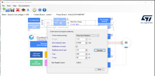
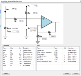
For your currents, and the opamps, your math looks fine, but as a sanity check, ST have released the Motor Control Workbench which can be used to calulate the gains. Your board is one of the options.
MCWB screenshot.png

MCWB screenshot2.PNG

You are correct about when to measure current, I advise using the injected conversion manager and triggering the ADC from the timer using the TRGO function at top dead centre (ARR-1, if you use ARR as the trigger it will not trigger...) You could look at my project to see the setup of the F401 timers and ADCs. There are a few ways to do it, mine works.

stancecoke said:
Especially the timing for the phase current measurement is quite tricky.
regards
stancecoke
It's fine to read sequentially. The loss of accuracy is acceptable, provided your ADC is running fast enough and you are not saturating your PWM. There's a lot of debate about this, and actually... the reality is that you can get away with quite a bit of time between the readings (on the scale of low single microseconds). I think the importance of the timing is quite over stated; just take care that at high speeds, you pick only the two phases with the most time "low" and use the identity Ia+Ib+Ic = 0 to simplify the clark transform and use only 2 phases.

You will need to calibrate the current offsets at stationary, zero current flow, or H bridge disabled. You also need to use centre aligned PWM if you are not already. This will probably (probbaly) fix your alpha-beta-0 transform issue. You always expect some degree of noise on the "zero" due to quantization, crappy opamps and ADCs, sampling offsets...

For sensorless, you can use this observer, which is trivial to implement. https://github.com/davidmolony/MESC_Firmware/blob/6341d56ab0a8b9c5d6f9a4fe0e2161d2c581aa9b/MESC_Common/Src/MESCfoc.c#L616
I also made more complex versions, on this branch, but there is not a lot of performance improvement and it is a bit trickier to understand, so I link you both.
https://github.com/davidmolony/MESC_Firmware/blob/52c01a27c461c1231d5f43183509b3417db6b1b3/MESC_Common/Src/MESCfoc.c#L501
I came up with it myself, Benjamin recently made it an option (default) for the VESC project and says it took him 5 minutes from starting to getting it running. He is quite good at motor control though mind you ;)

SVPWM will always be centered around half the bus voltage. Another name for SVPWM is "midpoint clamp", the math for deriving the commonly used SVPWM implementation is hand wavey, and ultimately is a simplification of the inverse park and clarke transforms and then finding the max and min voltages derived from that and centering them all around Vbus/2.

To align your encoder, apply a positive voltage in Vd with the angle fixed at 0, allow it time to stabilise and then zero your encoder. If this does not work, it's a code error, or your rotor is jammed or something is broken.

To make your motor spin the other way, if your FOC is written correctly, you just need to apply a negative Iq (since you have not yet got a current controller, this effectively means a negative Vq).

My last bit of advice is that the FIRST thing you should implement is over current and over voltage protection that disables (tristates) the H bridge until you manually turn it back on. When you lose synch/hardfault/... whatever, all the spining energy ends up on the Vbus and it blows MOSFETs from over voltage, or perhaps blows MOSFETs by effectively dead shorting them and massive current builds up.

Good luck!
 
Noobish "What is True FOC? " thread for reference

https://endless-sphere.com/forums/viewtopic.php?f=30&t=105139
 
@stancecoke No, I don't use the ST Motor Control Workbench. Didn't know it existed. I'll go check it out, but my goal is to still do everything myself without looking at or using anyone else's code. I tend to be a masochist that way, but I've found that that's the best way for me to learn something new. Thanks for posting the link to the ST paper--I'll go take a look.

@mxlemming Thanks for the hints, particularly the opamp gain calculator. That tends to confirm that my analysis was correct, and that's a big help.

One thing in your reply puzzles me, and that's when and how to sample phase currents. You said:

I advise using the injected conversion manager and triggering the ADC from the timer using the TRGO function at top dead centre (ARR-1, if you use ARR as the trigger it will not trigger...) You could look at my project to see the setup of the F401 timers and ADCs. There are a few ways to do it, mine works.

I'm using center-aligned PWM and am triggering the ADC using the TRGO function, but I don't understand why it should be triggered at top dead center (ARR-1). My understanding is that when you have shunt resistors in the low-side legs of the MOSFETs, you should sample current when the low-side MOSFETs are turned on, and for my implementation of SVPWM, that's either at the beginning or end of the PWM cycle, as that's when the high-side MOSFETs are off and, hence, the low-sides are on. If I triggered at ARR-1, that would try to read the currents when all three high-sides are on with no current flowing through the shunt resistors. Can you explain the reasoning behind triggering the ADC at TDC? I'm using compare channels 1-3 to generate the PWM for U, V, and W, and compare channel 4 to generate TRGO to the ADC. I'm setting CCR4 to 1 to trigger TRGO as soon as possible in the PWM cycle while the SVPWM generated waveforms are still in the t0 phase (with all high-sides off and all low-sides on).

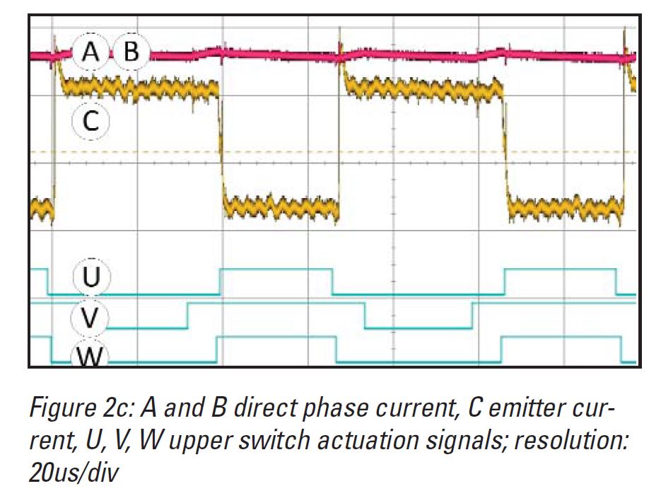
I found an article on the Infineon site that talks about current sampling in a three-phase motor control application and they have this scope shot:

Meas-Current.jpg


When they say "emitter current" they mean the voltage dropped across low-side shunt resistors. The PWM they show labeled as U, V, and W look just like my own PWM outputs to the high-side MSOFET gates. Their diagram shows the voltage drop (and hence, the current) is active when the high-side switches are off. This is what I'm trying to achieve with my TIM1/ADC setup. Please correct me if I'm off-base anywhere here! I'm far from being an expert on any of this.

Thanks for clarifying why the SVPWM generated waveforms are centered at half the bus voltage. I'll have to go back and look at the derivation of the equations and try to determine why/how this occurs.

Point well-taken on over voltage and current protection. My motor control board uses an L6230, which has built-in overcurrent protection and an output that I'm using as the BKIN input to TIM1 to shut down the drivers if an overcurrent event occurs.

Lastly, you said
To make your motor spin the other way, if your FOC is written correctly, you just need to apply a negative Iq (since you have not yet got a current controller, this effectively means a negative Vq).

I tried this, and it didn't work. The motor always turns CW no matter the sign of Iq. I don't understand this, because this should work. Here's a description of how my FOC implementation currently works.

1. Initialize TIM1, ADC1, the GPIOs that control the L6230 enables.
2. Zero the encoder position by energizing the V-phase and wait until the rotor stops moving.
3. Start the main motor loop.
4. An interrupt fires at the end of every PWM cycle (currently running at 10 kHz). In the interrupt handler, do this:
4.a. Read the encoder and convert to radians.
4.b. Run the inverse Park transform to calculate Iα and Iβ from the rotor position. Id and Iq are constants here, with Id set to 0.0 and Id set to some reasonable value.
4.c. Run the SVPWM code to calculate the PWM compare register values for U, V, and W passing it Iα, Iβ, and the rotor position.
4.d. Set TIM1's CCR1-CCR3 registers with the values determined in step 4.c.
4.e. Use the currents calculated from the ADC conversions to calculate Id and Iq using the Clark and Park transforms. These are calculated here, but not used for anything, except to display them.

The motor runs very well and very smoothly using this code, with the exception that it will only turn CW no matter what I set Iq to.

Here's how I do SVPWM:

Code:
void svpwm(float alpha, float beta, float theta, float Vdc, float T, float *Tu, float *Tv, float *Tw)

{

    float Vref, modulationIndex;
    float Ta, Tb, T0, sinTheta;
    uint32_t sector;

    Vref = sqrtf((alpha * alpha) + (beta * beta));
    modulationIndex = (Vref * PIOVER2) / Vdc;

    sector = 1;
    while(theta > PIOVER3) {
        theta -= PIOVER3;
        sector++;
    }

    sinTheta = sinf(theta);
    Ta = modulationIndex * (cosf(theta) - (ONEOVERSQRT3 * sinTheta));
    Tb = modulationIndex * TWOOVERSQRT3 * sinTheta;
    T0 = (T - (T * Ta) - (T * Tb)) / T;

    switch(sector) {
        case 1:
          *Tu = T * (0.5f * T0);
          *Tv = T * ((0.5f * T0) + Ta);
          *Tw = T - (T * (0.5f * T0));
          break;
        case 2:
          *Tu = T * ((0.5f * T0) + Tb);
          *Tv = T * 0.5f * T0;
          *Tw = T - (T * (0.5f * T0));
          break;
        case 3:
          *Tu = T - (T * (0.5f * T0));
          *Tv = T * (0.5f * T0);
          *Tw = T * ((0.5f * T0) + Ta);
          break;
        case 4:
          *Tu = T - (T * (0.5f * T0));
          *Tv = T * ((0.5f * T0) + Tb);
          *Tw = T * (0.5f * T0);
          break;
        case 5:
          *Tu = T * ((0.5f * T0) + Ta);
          *Tv = T - (T * (0.5f * T0));
          *Tw = T * (0.5f * T0);
          break;
        case 6:
          *Tu = T * (0.5f * T0);
          *Tv = T - (T * (0.5f * T0));
          *Tw = T * ((0.5f * T0) + Tb);
          break;
    }

}

This is an unoptimized version of the function as it's easier to follow. The inputs are Iα, Iβ, theta (the rotor angle in radians), Vdc (the DC bus voltage), and T (the value in the TIM1->ARR register). The outputs are Tu, Tv, and Tw (the values to put in the TIM1->CCR1 through CCR3 registers).

My inverse Park code is even simpler:
Code:
void InverseParkTransform(float d, float q, float theta, float *alpha, float *beta)

{

    *alpha = (d * cosf(theta)) - (q * sinf(theta));
    *beta = (q * cosf(theta)) + (d * sinf(theta));

}

Now that I partially have the motor phase currents under control, when the motor's running in steady state with no load (3600 RPM with 26 mA indicated on the power supply), the Iq and Id I calculate from the measured currents (and after the Clark and Park transforms) are now very steady. Iq is steady at -56 mA and Id is steady at 16 mA. The Id is curious--when I calculate updated PWM, I'm using Id = 0.0 for the inverse Park/SVPWM process. Could the fact that Id calculated from measured phase currents is not 0 indicate that my Iq vector is not 90° offset from the Id vector?
 
The top dead centre thing is simple... Normally pwm is on/high at 0 and stays high until it reaches CCR, when it toggle low.
Top dead center is therefore when the high side MOSFETs are off and low side are on, assuming you've set up the timer with positive polarity pwm. This might be opposite to what you initially expect.

Normally T1ch1 controls the top FET for channel 1 and T1ch1N controls the low side FET.

Your flow should go
Read currents at top dead centre (low side FETs conducting)
Run Clarke on currents to get Ia Ib
Run park on currents to get Id Iq
Use PI controller (or similar) to convert current error to a voltage in Vd Vq
Run inverse park to get Va Vb
Run svpwm or inverse Clark to get phase pwm values

Why it runs one direction only, no idea. Something's wrong in your code. Foc and svpwm definitely work both ways. You're not accidentally aligning the encoder 180 degrees off are you? Is the encoder input definitely set up right so that it counts in quadrature?
Lots of possibilities I'm afraid.
 
@mxlemming Ah, you’ve got the timer that generates PWM set up in what ST calls PWM mode 1. In that mode, the output is high while CNT is less than CCR while counting up and low while CNT is greater than CCR when counting down. I’ve got mine set up in mode 2. With mode 2, the output is low while CNT is less than CCR when counting up and high while CNT is greater than CCR when counting down.

I’ll switch to mode 1 and see how that works. The CCR4 TRGO signal with CCR4 set to ARR-1 is probably a more definitive way to make sure all of low-sides are on. Should simplify the duty cycle calculations too as I won’t have to subtract the counts from the ARR contents.

Thanks for the clarification on FOC flow. I’m not quite there yet as I’m not controlling Id and Iq yet. For now I’m just feeding them as constants into the inverse Park transform to calculate alpha and beta to feed the SVPWM code with. I am calculating Id and Iq, but just to see what they are—I’m not feeding them back into the front end of the FOC code.

Yes, my encoder is definitely generating quadrature output and the timer I’m reading it with (TIM2) is definitely counting properly. I tested it by spinning the motor by hand and it counts as expected, both ways. I’m not sure what you mean by aligning the encoder 180 degrees off. Can you elaborate on that? What I’m doing is energizing one of the phases briefly until the rotor settles down and stops and zeroing the counter there. Could I be 180 degrees off as a result of this start-up process?

Thanks for taking time to answer my questions.
 
I can't immediately imagine mode 1 vs mode 2 would matter except for trgo going to arr =1 and the math being a bit upside down.

The backwards encoder alignment is just a guess because I've been having issues recently with HFI and it running backwards because it has to guess which 180 degrees it's looking at (saliency tracking struggles to tell the difference between North and South poles)
 
Breville said:
but my goal is to still do everything myself without looking at or using anyone else's code. I tend to be a masochist that way, but I've found that that's the best way for me to learn something new

That was exactly my way, every line of code written by myself (beside the peripheral setup, generated by CubeMX) and everything without use of floats, as the processor I use has no FPU :shock:
With a faster processor with less ADC sample time, the timing of phase current measurement gets less critical. But with the STM32F103 (same as on "bluepill"- boards) you don't get proper readings at above 70% duty cycle without some tricks explained in chapter 5 of the linked paper....

regards
stancecoke
 
@stancecoke Yes, that’s how I like to work too. I don’t use the ST HAL libraries. I write every line of code myself from the first instruction the MCU executes after reset to everything that initializes and manages the peripherals—it’s all mine. I understand every bit of it and have only myself to blame if something doesn’t work right. I’ve not been impressed with most vendor libraries—some of them seem like they were written by summer interns and are abstracted to a ridiculous extent.

I’m using a part with an FPU, so I’m doing most things in float. The STM32F401 is fast enough so this isn’t an issue, and when I design my own boards I’ll use either an STM32F7 or an H7, which will have much more performance.

I’ve added a simple optimization when measuring phase currents. I use the current measurements from the two phases with the lowest duty cycles and calculate the third using Ic = -Ia - Ib.

@mxlemming I plan to take a very close look at my encoder handling code today looking for anything that might be affecting the ability to run the motor in the opposite direction.

I discovered another interesting thing overnight when I left the motor running and logging RPMs on a graph. The motor will cyclically slow down and speed up on a 10-15 minute period, with the RPM varying by +/- 25 RPM (when running at 3600 RPM). I don’t know if this points to some issue in my code, but it’s certainly interesting and worth investigating.
 
I just checked the operation of the quadrature encoder on my motor and it behaves as follows:

With the encoder count zeroed, turning the motor shaft CW results in it counting 0,1,2,3,4,5,6...358,359,0,1,2...

With the encoder zeroed again, turning the motor shaft CCW results in it counting 0,359,358,357...3,2,1,0,359,358...

(Actually, it counts 0,1,2,3...3998,3999,0... and 0,3999,3998,3997...3,2,1,0,3999... since it's a 1000 count-per-turn encoder and the STM32 timer counts every edge, so four of them per count and 4000 per mechanical revolution. I convert that to electrical degrees between 0 and 360 taking the number of pole pairs into account.)

Perhaps the SVPWM code is expecting it to count like this when the motor turns CCW: 0,-1,-2,-3...-358,-359,0,-1,-2...

This shouldn't matter because my SVPWM code will use the correct sector in either case.

I'm just thinking out loud here. Getting the motor to turn in both directions is my priority now.
 
Breville said:
I eventually want to create my own motor controller for an eBike
I don't know any commercial EBike motor, that has an high resolution encoder. So your recent efforts have educational character surely, but won't help you with an EBike project.
EBike motors have three hall sensors for the rotor position normally. There are various strategies to estimate the recent rotor position from the 6 possible hallstates. E.g. in the neighbour thread:
https://endless-sphere.com/forums/viewtopic.php?f=30&t=114537

regards
stancecoke
 
@stancecoke Yes, I know that most motors usable on an eBike are either Hall sensored or sensorless, but I figured implementing FOC on a motor with a high-res sensor would be easier than working out the details of a flux observer or another way to synthesize rotor position and would avoid complications that I’d rather not deal with in the beginning. Small steps, small steps…

I plan to approach this in three phases: getting FOC working on the bench with small, low current sensored motors, then using that experience to develop the traction system for a 1/3-scale replica of the Curiosity Mars rover that I’ve been working on (this will use six small motors with high-res quadrature encoders and motor controllers that I plan to design and build) and then move on to either an eBike or a go-cart.

I think I’m making good progress so far. I’m running into issues, but am gradually resolving them and moving forward. I recently acquired a dyno, and that should help me make faster progress.
 
Some additional progress… When I started this project, I wanted to use the X-NUCLEO-IHM08M1 daughter board with the Nucleo, but it was out of stock everywhere and I had to settle for the X-NUCLEO-IHM07M1, which is 2A board versus the 08, which is 15A. Earlier this week I found a distributor that had the Infineon XMC4400 drive card/250 watt motor drive power card combo in stock and they arrived yesterday morning.

I pulled an all-nighter last night and succeeded in getting both 6-step and FOC working on these boards. Although I’m more familiar with the STM32 than XMC4000, I know the Infineon MCUs well enough that this wasn’t overly difficult. In fact, in some ways the XMC parts are better suited to motor control as the CCU8/CCU4 timers, the VADC (four separate ADCs rather than just one on the STM32F401!), and the dedicated POSIF position interfaces are more flexible and configurable than their STM32 counterparts (and the Infineon documentation is better written than the ST stuff). 120 MHz vs. 84 MHz is nice as well.

6-step was much more difficult than FOC on this combo due to the over engineered German approach to POSIF Hall mode—it probably took me 10x the effort it took to implement it on the STM32. Getting FOC working, in comparison, was relatively easy. The biggest issue I faced was how to interface the single-ended quadrature encoder on my motors to the differential encoder inputs on the board. I finally ended up bypassing the board’s encoder interface and connecting the sensor outputs directly to the POSIF interface.

This should give me more margin when working with my new dyno, which has larger motors than the tiny ones I’ve been using so far. If 250 W isn’t enough, Infineon has a 750 W motor control kit I can try.
 
I actually agree with your strategy with the encoder, I spent so much time messing about with hall sensor interpolation and sensorless that would have been much better spent on current control loops and better transform implementation.

Once you have the current control running well with the encoder, sensorless just drops out in like 10 easy lines of code

I'm interested to see how you approach the Infineon code. I built an infineon based ESC using an xmc4100 and it works pretty well with their library but i find the timer incredibly confusing compared to the st one and the ide is rather tricky and incomplete.
 
The Infineon XMC definitely has more complex timers than the STM32, but once you get used to them, and how they interact with other peripherals like the VADC, they’re not so bad. In some ways I find the Infineon implementation more logical and flexible than ST’s. You can do things with them like chaining them to create 32-bit, 48-bit, and 64-bit timers.

I don’t use vendor IDEs. For ARM MCUs, I use CrossWorks for ARM by a UK company called Rowley. It’s a much cleaner and faster product than most vendor IDEs, which tend to be based on Eclipse (which I find slow and ponderous). CrossWorks isn’t free, but they do have a $150 personal license for non-commercial use.

Segger has licensed CrossWorks from Rowley and sells it as Segger Embedded Studio, and it’s free for non-commercial use. It’s the exact same product as CrossWorks, except Segger has removed support for all debug hardware except their own J-Link. Most Infineon dev boards come with built-in J-Link Lite, which works well with Embedded Studio. Segger also has free firmware that will convert the built-in ST-LINK on ST’s Nucleo and Discovery boards to J-Link, making them compatible with Embedded Studio.

For most debugging, I use Segger’s Ozone debugger rather than the IDE’s debugger.
 
I just figured out why I can't get the motor to spin both ways. It's obvious and it was staring me in the face, but I just couldn't see it despite looking at it many times.

So, to get the motor to spin in the opposite direction should just require a negative Iq. That's obvious. But after calculating Iα and Iβ from Id and Iq using the inverse Park transform, my SVPWM code does the following:

Code:
    Vref = sqrtf((alpha * alpha) + (beta * beta));
    modulationIndex = (Vref * PIOVER2) / Vdc;

    sector = 1;
    while(theta > PIOVER3) {
        theta -= PIOVER3;
        sector++;
    }

    sinTheta = sinf(theta);
    Ta = modulationIndex * (cosf(theta) - (ONEOVERSQRT3 * sinTheta));
    Tb = modulationIndex * TWOOVERSQRT3 * sinTheta;
    T0 = (T - (T * Ta) - (T * Tb)) / T;

Notice how Iα and Iβ (called alpha and beta in the code) appear in only one line of code in this function?

Vref = sqrtf((alpha * alpha) + (beta * beta));

Squaring anything results in either zero or a positive number, and never a negative number, so there's no way this code can generate waveforms that will run the motor in the other direction. Now I just need to figure out a way to fix this...
 
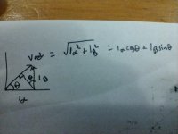
You've already got the sin and cos angle so isn't vref something like alphaxsin+betaxcos (or vice versa, typing from my phone)
IMG_20220605_214721268.jpg

I'm also a little dubious about your sector identification method. It probably works in open loop but the question is where's your theta from? If it's from atan2(Valpha Vbeta) this probably works, but normally in FOC theta refers to the rotor (encoder) angle which is not the same due to rotor inductance. I don't know what's going on in the rest of your code but i don't think this will work when you close the loop
 
Breville said:
Squaring anything results in either zero or a positive number, and never a negative number, so there's no way this code can generate waveforms that will run the motor in the other direction. Now I just need to figure out a way to fix this...

My non-programmer brain says:

how about having a check right there for whether reverse is selected or not, and if it is, just turn the necessary numbers negative?

Or of the check and math would slow things down too much, then whenever reverse is selected, a completely separate routine (or branch) is used that just has the negative-making code right after the code that makes the numbers.
 
@mxlemming The value of theta that I'm passing into the SVPWM function is the electrical rotor angle as measured by the encoder.

When I calculate an angle via atan2(Iβ, Iα), I get an angle that always trails theta by 90 degrees (ex: theta = 169 degrees, angle calculated from atan2 is 79 degrees, which is lagging theta by 90 degrees).

Calculating Iα*cos(theta) + Iβ*sin(theta) when using theta (the encoder-derived angle), always results in 0.0 and is not what the calculation of sqrtf((Iα*Iα) + (Iβ*Iβ)) results in.

However, when I calculate an angle using atan2(Iβ, Ia) and plug that into Iα*cos(theta) + Iβ*sin(theta), I do get the exact same result as sqrtf((Iα*Iα) + (Iβ*Iβ)).

I'll have to ponder this and try to understand its meaning. The fact that one of the angles lags the other by 90 degrees is probably significant as the direct and quadrature axes are supposed to be 90 degrees apart for max torque generation.
 
I should point out that above i made a whoopsie...

We do not feed the svpwm with currents.

Svpwm gets fed voltages, so where i wrote ia and ib that should be Va and Vb.

To my previous point... The rotor electrical angle and the stator electrical angle are not the same. Using the rotor electrical angle for svpwm sector identification won't work.

I sidestepped this whole svpwm thing and used the inverse Clarke transform, svpwm is not intuitive and doesn't seem to be any more computationally efficient than the full transform.

It still plays with my head that the voltage generated by the motor and the angle of the rotor are 90 degrees apart. It makes thinking about this quite hard.
 
mxlemming said:
Using the rotor electrical angle for svpwm sector identification won't work.
Why shouldn't that work?! With the SVPM approach given in the ST paper, it works flawlessly in both rotation directions. No need to fiddle around with atan2 functions. There is only the one issue with the inverted sinevalue in the inverse park transformation.
https://github.com/EBiCS/EBiCS_Firmware/blob/c9f0419845757791882f35be27c163f86745d70b/Src/FOC.c#L159

regards
stancecoke
 
stancecoke said:
mxlemming said:
Using the rotor electrical angle for svpwm sector identification won't work.
Why shouldn't that work?! With the SVPM approach given in the ST paper, it works flawlessly in both rotation directions. No need to fiddle around with atan2 functions. There is only the one issue with the inverted sinevalue in the inverse park transformation.
https://github.com/EBiCS/EBiCS_Firmware/blob/c9f0419845757791882f35be27c163f86745d70b/Src/FOC.c#L159

regards
stancecoke

You're not using the rotor electrical angle in that svpwm implementation.

You're using the Ys and Zs and if else statements.
 
Back
Top