Advice needed: Adding Rear Suspension to CrazyBike2

amberwolf

Administrator
Staff member
Joined
Aug 17, 2009
Messages
40,859
Location
Phoenix, AZ, USA, Earth, Sol, Local Bubble, Orion
file.php


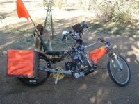
This adds about a foot to the length of the bike, and about 15 pounds (so much for making it lighter) but it appears to be going ok so far.

Original:
View attachment 5

New:
View attachment 4

I've got several options for doing this, and this is just the first attempt, doing it the "easy way", that lets me revert back to the original at any point, without cutting into the original rear triangle. There are certainly better ways of doing it, but because of the cargo pods, they all require severe modification of the whole rear end that would preclude going back if it doesn't work out.

*This* method allows me to even undo it when I'm on the road, if something breaks unfixably on a longer test trip, though that would be pretty annoying and take at least an hour to do.

It starts with the 24" rear triangle originally slated for the unfinished ReCycle, and bolts it's crankshaft/BB to the dropouts of the CrazyBike2's rear triangle, in place of the wheel. The wheel now goes into the new triangle.
View attachment 3
Then a shock with coil-over spring, origin unknown but possibly motorcross bike, bolts to the top of the new rear triangle, pointing forward to align with the top of the original rear triangle/toptube to keep all the pushing forces along a strong line.
View attachment 6
The front mounting point for the shock is adjustable, to give me about two inches of adjust range, for altering rear end height when loaded if it is necessary. I did this by cutting a strong hard steel plate off the bottom of a heavy desk chair to weld to the square-tubing that supports the cargo pods and seat, as that is the strongest point on this section of the bike.
DSC02194 reartopview closeup front pivot adjust.JPG
I bored a hole in it large enough for the steering tube from a discarded Razor kick scooter to fit thru, with the "fork" end pointing rearwards. I threaded the top nut for the tube on it's "rear" end, behind the plate, and the locknut on the "front" end in front of the plate. Those are what let me adjust it's length, and secure it to the bike.
DSC02188 suspension idea alignment.JPG
The fork bolts thru the front pivot of the shock. The rear pivot bolts to two more small pieces of plate welded to the rear triangle just in front of the seat stays.

The preloading will be done by a tub-balancing-support cable off an old washing machine which will restrict how far the bike can pop back up after I get off of it, which will normally be sagging loose during the ride, so it will only ever have a load on it when it's not being ridden. It's main purpose is to keep the chain from ever having to rub on the frame, and so I can see what the bike is like when I am not on it, plus not having to climb up so high onto the seat. :) The shock itself doesn't have a preload method built in.
DSC02193 closeup reartopview suspension.JPG
The spring compresses about 2/3 of it's length with me on it, leaving a bit for bumps and whatnot. If I have much cargo in the pods, it will compress most of the rest of the way, unfortunately, requiring a different leverage method for the spring to use it properly. I'm mostly doing it this way now so I can easily undo it, and because this method is easy to build and test.


Now, chainlines I'm still working out, so stuff may change as I do this. In theory with the spring preloaded by cable, the chain should pass normally thru both triangles to the rear wheel. That might not work perfectly thru the gear range at the back, so I might need to add a guide wheel to get around the stays. Hope not, but....

There is also a second derailer used only for it's tensioner, at the original dropouts. It's there solely to take up the slack as the triangle moves back down, and provide enough extra chain that I don't need to worry about the actual rear derailer jamming due to chain overtension when I'm on big ring front plus big ring rear on the occasions that must happen.
 

Attachments

  • DSC02164  full bike right side view.JPG
    DSC02164 full bike right side view.JPG
    41.9 KB · Views: 3,882
Ok, I already had a problem (of course). The steel plate the whole thing goes thru under the seat is great when pushing against it, but apparently not in pulling.

I didn't take a pic of it, but when I sat on the seat and started bouncing up and down to see what would happen (before I put this thing on the road), at full compression the angle of the shock is just above and down onto the front pivot point. That forced the pivot to pull on the plate rather than push against it, and the whole assembly sort of folded down into the empty original rear triangle.

So I'll need to do some rethinking on this. I have a 1/4" steel bar that I put under the pivot point across the square tubing for the cargo rails, and this prevented it from happening again, but I don't want to add essentially another pound just for that--plus eventually that might bend, too.

What I will probably do is move the rear pivot point downward closer to the BB, so it is always pushing upward against that plate, or even better against a pivot point that is part of the cargo pod rails. That would actually counter the weight of cargo in the pods pushing down on them, and if the pivot point joins the rails horizontally it will also stiffen that part of the frame.

Chainline currently does not come out right, so having to rework this is actually helpful. I might wind up putting a large sprocket (to reduce noise) on a jackshaft in front of the rear wheel, between the cargo pods, to keep the top of the chainline clear of both sets of stays even during pivoting.
 
amberwolf said:
The spring compresses about 2/3 of it's length with me on it, leaving a bit for bumps and whatnot. If I have much cargo in the pods, it will compress most of the rest of the way, unfortunately, requiring a different leverage method for the spring to use it properly. I'm mostly doing it this way now so I can easily undo it, and because this method is easy to build and test.

why not use a longer bolt through? then hang both shocks side by side on the longer bolt?

if you bottom a shock out, you can damage the valve inside, so best if it doesn't sit 2/3 compressed. Motorbikes had 2 because it takes 2 to support a person's weight.

Since you left the seat tube in place, you could make a bracket out of a seat post to adjust the spring rates of the double shock. slide it up higher for more firm ride, or down for a softer ride.
 
will_newton said:
Mad Max called, he wants his e-bike back. :D

Nice Hack!
:lol: He won't want it until I finish figuring out the rocket launchers and stuff. ;) (there are times I wish....)


Drunkskunk said:
why not use a longer bolt through? then hang both shocks side by side on the longer bolt?

Mostly I did not use both because of their weight. This monster is already 150 pounds *before* I started this part of the project, and will be at least 180 afterwards, including a fourth SLA for 48V. But that probably increases the need for both of them....

I don't have a long enough single bolt that is likely to take the forces involved, so I will need to make a double mounting point that lets me use two shorter bolts side by side, to mount both of them. Maybe I can just make a 3-plate mount that supports the bolt in the center and still use the longer but not-as-strong bolts.

if you bottom a shock out, you can damage the valve inside, so best if it doesn't sit 2/3 compressed. Motorbikes had 2 because it takes 2 to support a person's weight.
I had been hoping that one would be sufficient, as they are heavy. I was thinking that part of the reason this ends up compressed so much was because of the leverage the rear wheel has on it from the position and angle I have it mounted at, but that's probably not the case.

These shocks have a 1/2" rubber bumper on the shaft to prevent it from actually bottoming out. I'm pretty sure the valves and such inside are not in anything like "new" condition anyway, seeing as I found them at the thrift store for super cheap.


Since you left the seat tube in place, you could make a bracket out of a seat post to adjust the spring rates of the double shock. slide it up higher for more firm ride, or down for a softer ride.
Now THAT is a really good idea, and much better than any of the other ideas I already had that I haven't tried yet. Especially since this is a cargo bike, and will need to be adjusted for height when heavily loaded down.

Although I think it will end up the opposite--down for firmer (preloading the springs more) or up for softer (less pre-compression), if I understand correctly. The forward part of the mount would then not be where I have it now, but instead would be much closer to the new triangle's BB/pivot point, down by the dropouts of the original rear triangle. (If I don't do it that way, it'll be in the way of cargo that needs to go across the tops of the pods).

As soon as I'm done with dinner for me and the dogs and puppies, I'm going to go explore my junkbins for stuff necessary to implement a version of that, and see if it works.

I'm not sure I can do it with two shocks side-by-side though, as there is not much room in there. And I don't think I could make it work with one in front of the other due to pivot points, unless I put them both on one pivot plate and had the plate pivot instead.

Of course, after I'm done with getting the suspension to work, then I have to come up with something to ensure the chain goes around the stays, and it has to be VERY tough, because this motor can pull VERY hard VERY fast--it's already destroyed one chainring and damaged another.

I also have this front motorcycle fork:
http://electricle.blogspot.com/2009/06/forks-sporks-springs-dorks.html
which would even with just one be a pretty good shock absorber, but it's way too long and heavy for this thing.

I *am* considering building a dualie rear wheel around an axle made from that steering tube bearing holder, though, plus those bearings or something similar. I doubt I would have breakage problems with *that*. :lol:
 
This is my adaptation of Drunkskunk's idea:
Drunkskunk's adapted idea.PNG
where purple is the original frame, brown is the load-bearing cargo rails, orange is the new triangle, gray is the seatpost, and red/black is the shock and spring.

Also, this post:
http://electricle.blogspot.com/2009/12/adding-rear-suspension-to-crazybike2.html
has the basic idea of this thread in it, plus a few extra pics. I'll keep adding to this thread, and make a new blog post once there is enough to add to it.
 
Amberwolf,
Good work. My hardtail is killing me too, and have just been planning the easy route using 2 motorcycle shocks I have in a normal manner. You've got me thinking about maybe giving monoshock a go. You have now surpassed the Pakastani guy. I with you, when our ebikes are basic transportation reliability and functionality are the only things that really matter.
John
 
Don't go giving me any kudos yet--it still doesn't work! ;)

I've been trying out various versions of the last scheme above, and when I have time (maybe tonite after work) I'll post some pics. But I managed to break the original rear triangle already, due a very stupid idea I didn't fully consider before attempting. :(

The good news is I can fix the damage (bent seat stay), but the bad news is that so far none of the ideas will quite work. I think I'm going to *have* to go dual-shock. In order to do that, I will need to make a spring-retention disc for the second shock, as I only had one of the cutting wheels like that.

The next thing I have to do is create a plate for each side that connects the cargo pod rails to the rear triangle, and bolt the shocks to the plate. Otherwise there is not going to be enough strength in the rear triangle for it to deal with the load using the angles I have for everything in the drawing above.

I think that what I really need to do is to shorten the orange rear triangle, heightwise via cutting the seat tube down, then bend the seat stays down to where their join point would line up with the cargo pod rails, and put the rear shock mount there, so it presses against the strong joint. Then put the front end of it back where I started from, to the strong join of seattube/toptube of the main frame.

Otherwise, I don't think anything I do to the thin tubing of the original rear triangle is going to help it much, in withstanding the downward forces on it, which are the weight of the bike, rider, and cargo, multiplied by whatever force the lever action has on it (which I don't know how to figure out--me and math don't really get along very well).
shortened triangle.png
 
Wow, you are a true chop-shopper aren't you? That's an incredible piece of out-of-the-box thinking!

Just curious, what kind of wheel did you put on that thing that can support yourself + the 180 lbs of frame components and the batteries? I've been busting spokes left and right and really am tired of dealing with it. I've been looking into a tandem touring wheel as well, but they are not cheap.
 
dequinox said:
Wow, you are a true chop-shopper aren't you? That's an incredible piece of out-of-the-box thinking!
My problem is that no one ever told me there *was* a box. ;)

By the time I figured out there was supposed to be one, I'd already turned mine into something else. :p


Just curious, what kind of wheel did you put on that thing that can support yourself + the 180 lbs of frame components and the batteries? I've been busting spokes left and right and really am tired of dealing with it. I've been looking into a tandem touring wheel as well, but they are not cheap.
Well, that's the thing--I keep breaking rear wheels all the time, because there isn't any suspension for it. The front one is fine, even though I've hit the same potholes with it that I have the rear wheel. And the first pair of wheels were both off the same Roadmaster bike; the front one is still the same one. But it has a suspension fork (off the Roadmaster), so it doesn't have to take the beating the rear does, even if I hit potholes and rocks or road debris while braking suddenly.

I've bent two axles (I just left the bent one on there last time; it's not really making anything worse), at least three rims (one I managed to fix), and broken enough spokes that I forgot exactly how many, but I ran out of spokes to pull off of one old wheel's drive side, so at least 18 of them on that side, and maybe 3 or 4 on the left side.

I've broken more pull spokes than push, and almost all of them since putting the new motor on there. It just has so much torque that it really stresses them out, and then they break a lot easier when I do hit bumps and holes.

As mentioned above, I'm looking into building a completely custom rear wheel for this thing, that will have two rims, two tubes, and two tires, but one axle with two large-diameter flanges, each with 36 holes. Then I can lace each rim across both sides. It'll have twice as much support, plus if I blow a tire I don't have to change it right away, *and* I get double the stopping power and drive power due to a doubled contact patch (except during turns). I'll probably leave each rim independent of the other, for a tiny bit more road-conforming suspension/traction.

But that'll be a while; I need to work out a suspension system first. Today was a miserable failure, since not only did I not find a workable method yet, I actually broke the original bike frame, making it impossible to even go back to start point until I repair it. :(
 
*
 
Affliction said:
But that'll be a while; I need to work out a suspension system first. Today was a miserable failure, since not only did I not find a workable method yet, I actually broke the original bike frame, making it impossible to even go back to start point until I repair it. Watch me build an electric bike from assorted junk!
Damn! I usually plan things before I start modifying. Your bike with the suspention mod is an abomination.
Good idea but poorly implemented. I cringe at the thougt of you bulding a bike :shock:
Don't give up on the Extracycle type swingarm; The bottom bracket has good sturdy bearings.
You need a bracket to attach the dual car shocks with springs from the seatpost on the rear section to the seatpost on the original bike.
This will make it removeable and ajustible by changing the height of the rear seatpost stem.
if you know geometry then you know what i mean.

Whoever said on another thread that you need to lose the attitude is right. :( You know how to DIScourage people pretty well--why not try turning that around and ENcourage them instead? Or perhaps you're the kind of guy that loves to have people shit on him when he's having fun trying to do something he's never done before?

You certainly don't have the attitude I'd expect from *helpful* forum members.

As an aside, if you actually *read* the posts, I started out with essentially what you are suggesting, I just didn't have strong enough metal for the plate at the front seatpost.

But I think you're having too much fun crapping all over the ES forums to read anything thoroughly. "Affliction" is a good name for you. :roll:
 
I am about to start the repair of the bike frame from my stupid mistake, and at the same time replace the insufficiently-strong metal plate I started with in the first concept with some of that 1/4" steel plate, which should fix the main problem I had with it. I'll also be taking off my not-so-great adjuster idea with the Razor fork, and just putting 1/4" thick pivot points there.

I'll also be shortening the rear triangle that pivots, so that the entire shock should stay below the cargo pod tops even during bottom-out.

Then I will use the seatpost portion of Drunkskunk's idea to make a slightly-adjustable ride-height, but with a twist.

I'll weld the removed portion of the seatpost (or other tubing to do the same job) horizontally in front of the seatstays, so that I can still adjust the shock length/ride height per his idea.

I will also have to use both shocks as he said; one of them simply can't handle the weight of this thing, no matter which way I try it.
 
Hey amberwolf. The new design looks much more workable. Here's a guesstemate for the math. You + bike are about 400 lbs and roughly 200 on each wheel. The force on the wheel will be about 1G while it hits a hole or bump ( roughly 1 inch) so that will mean 1G + weight on wheel will be about 400 lbs of force. For spring rate calculations look here:


http://autospeed.com/cms/A_2939/article.html

He is the master, Lots of mech engineer stuff made really quite understandable!
I hope this helps some.
otherDoc
 
Yeah, that site is what first made me look into suspensions, recumbent trikes (which led me to this bike), etc. However, I get lost and confused when reading thru the math parts. It just starts to make my mind go blank as I read, as if I were reading a dead untranslateable language interspersed with English. :(

This kind of thing is what stopped me from becoming an electronics engineer instead of just a technician; even the math sometimes necessary as a tech is overwhelming and keeps me from doing some things. But the engineering math I usually don't even begin to comprehend. I have similar problems with learning programming. I think it has to do with manipulating symbols--I don't seem to do that very well unless I have some real-world things I can relate them to and associate them with. For most math, there is no way for me to do that (not just things like using 3 oranges and 4 apples, but something else, which I can't define because I don't know what it is).

Experimenting with the suspension physically shows me a LOT of things, that I then understand, but I still don't seem able to associate the math with the physical actions. I think I need to be physically present with someone who does understand the math of it and physical examples of each suspension type to be *shown* how they relate to each other, in realtime, in motion. I've already tried to understand it by drawing it out, but it does not mean anything more to me than the math alone did. I don't know how to continue further down that path without just playing with it....

(as an aside, what I REALLY wanted to be when I was a kid was an astronaut or a spaceship engineer, but I could not grasp the relatively simple math of orbital mechanics and whatnot, still can't, although I can intuitively *see* what would happen if certain things occur, I cannot numerically work it out).


EDIT (ADDED): oh, and another problem I have is that as far as I can understand it, what all the places that show how to figure out what springs to use for a given suspension do is not what I actually need, which is to figure out how to use the springs I already *have* to get a suspension that will do something close to what I want. ;) I know that mathematically there must be a way to flip the formulas around to figure this out, and to measure what my spring rates actually are since I don't know, but that is beyond my abilities to figure out. Unfortunately being "smart" doesn't have anything to do with being able to grasp certain things; my mind simply does not quite work like most peoples--it is broken in a few ways that kind of make me an alien to some stuff.
 
At DIY electric car you said:

"I host the images usually on my blog, which uses the free Picasa web service from google to host the actual images. Sometimes I have forgotten and ended up only having it hosted on another forum, like the ES forum (which allows and encourages images to be uploaded directly rather than externally linked). Then I copy the URL for the image itself, and paste that into my post. I select the URL, and click the little yellowish postcard with mountains on it in the message editor toolbar, which puts IMG tags around it.

One could insert the tags first, then paste the URL to the image between them, and that works too. "

Re: "Then I copy the URL for the image itself, " how do you copy a URL? I don't know what a URL is (or tags)
 

Attachments

  • trike cargo design.JPG
    trike cargo design.JPG
    28.1 KB · Views: 3,105
mxmtech said:
Re: "Then I copy the URL for the image itself, " how do you copy a URL? I don't know what a URL is (or tags)

Ah, sorry. A URL is the link to something on the web, like http://www.diyelectriccar.com/forums/search.php?do=getnew is the link to see all the new posts on DIY Electric Car forums, and http://www.endless-sphere.com/forums/download/file.php?id=30978 is the link or URL to the image you posted above.

If you right click on almost any image on the web, your browser should have in the little menu that pops up the option to "Copy Image Location" or "Copy Link Location", "Copy URL", "Copy Target Location", or something similar. Firefox uses the first of those to put the URL of the image in the clipboard, so you can paste it into a post on a forum or an email or wherever you want to.

As for tags, they are just the things forums and browsers use to know how to manipulate the text you type in (or paste in) to display it correctly.

In most forums, ES and DIYEC included, the message editor has buttons just above where you type your message to do various things, and they are done internally by putting tags at the start and end of whatever you are changing.

This includes Quote, so that others can easily distinguish someone else's words from your own, when you quote others, since just using " " marks can get kind of lost in long messages (especially mine). That's what I used at the top of this post to quote you, by copying and pasting that part of your post into mine, then selecting the text and clicking the Quote button.

Image tags are similar, so that if you have an image you either can't upload or don't want to, you can link to wherever it is on the web instead, and have it still display as an image.

Actually uploading the images using my blog is easy; same thing using Picasa's website itself. I don't use the Picasa program, as it has behaviors I don't like that I can't turn off.


As for the trike design itself, I'm not quite sure how it's suspension and cargo basket (?) are intended to work, but it looks like it would pivot just behind the seatpost and be sprung right at the rear axle? That'll give suspension for any cargo, but it doesn't do anything for the rest of the bike's mass or the rider. You might not intend or want to do anything other than suspend the cargo, in which case that's fine. :)
 
Amberwolf,
I can relate to your advanced math blockage. Its something I came to much later in life. I blame it on being a rebel without a cause more than anything. I did try to contact my HS math teacher to apoligise for the constant debates we had over the "every day practicality of advanced math". I was too late. Maturity has a price.

Any way Here is a link to a suspension method that is fairly reasonable, I thought. Give it a look over, I hope it helps. Keep that creation roll, roll, rolling along. the good stuff starts on page 12. good luck! T
http://www.wind-water.nl/rec_build_booklet.pdf
 
If you right click on almost any image on the web, your browser should have in the little menu that pops up the option to "Copy Image Location" or "Copy Link Location", "Copy URL", "Copy Target Location", or something similar

This is what I get if I right click
 

Attachments

  • Untitled 2.jpg
    Untitled 2.jpg
    21.3 KB · Views: 3,029
it looks like it would pivot just behind the seatpost and be sprung right at the rear axle?

Springs and shocks to support the cargo box which extends about 1/3 past the rear axel. There is no attempt at scale in this drawing

That'll give suspension for any cargo, but it doesn't do anything for the rest of the bike's mass or the rider.

put all the batteries and electronics in the cargo basket and it doesn't leave much bike mass that isn't covered. just use a discarded bike that already has seat suspension or design a separate system for the seat

The design in Thud's post is really professional
 
Thud said:
Amberwolf,
I can relate to your advanced math blockage. Its something I came to much later in life. I blame it on being a rebel without a cause more than anything. I did try to contact my HS math teacher to apoligise for the constant debates we had over the "every day practicality of advanced math". I was too late. Maturity has a price.
I wish mine was caused by that, but I always liked *trying* to understand math, I just don't "get" it. It never made sense to me, but since I discovered my Asperger's I have wondered if the part of my brain that is broken by that is also used for conceptual math. I don't really know much about how the brain is wired up; hasn't been one of my areas of practical research (too many things I want to know and not enough time to learn them all, so I have to stick to things that I can *use* or at least potentially do something with).

Any way Here is a link to a suspension method that is fairly reasonable, I thought. Give it a look over, I hope it helps. Keep that creation roll, roll, rolling along. the good stuff starts on page 12. good luck! T
http://www.wind-water.nl/rec_build_booklet.pdf
WOW! :shock: I actually UNDERSTAND that, I think! I need to go over it again but it makes sense of some of the concepts I've read elsewhere, and best of all it has a method to help me figure out the properties of the springs I already have, and how to use them based on those properties, instead of working out what properties I need and then having to find a spring that fits those.

Thank you!

mxmtech said:
This is what I get if I right click
That's strange. I don't use Internet Explorer anymore, and the last one I used was v6, but your menu looks similar to what I recall. The only way I see on that menu for you to get the image URL is to select Properties from that menu, then in the dialog that comes up there will be an Address (URL): section, where you can then select and copy the text.

Perhaps I have become too spoiled with Firefox and assume all the other browsers do the same things. ;)


mxmtech said:
Springs and shocks to support the cargo box which extends about 1/3 past the rear axel. There is no attempt at scale in this drawing

Ok. Looks like it makes sense, it's just not how I would do it. ;) Then again, I'm crazy and build very crazy things! :lol:

put all the batteries and electronics in the cargo basket and it doesn't leave much bike mass that isn't covered. just use a discarded bike that already has seat suspension or design a separate system for the seat

I suppose so. I'm too used to dealing with the heavy bike frames I end up with, most of which are thick cheap steel tube, rather than light strong thinwall cromoly. Thus what I can make from them needs suspension to lighten the unsprung weight just to minimize the stresses on the frame itself, as well as rims and spokes, from all the things the suspension would absorb instead.

The design in Thud's post is really professional
Yes, it is, and best of all it's done in a way that even *I* can understand! :)
 
I had to go somewhere today, so I had to revert to the original bike and do the repair mentioned previously, so I didn't get any other versions worked out or tested yet. So in lieu of that, here's a post about the repair itself:

Here's the broken stay:
dsc02198 crushed stay side.jpg

dsc02199 crushed stay top.jpg
On the righthand stay is the prior attempt, which was not long enough; I decided to try one a little farther forward and longer, but being farther forward it had zero support from the dropouts and just crushed the tube as soon as I put the suspension together and let the bike's weight on it, and pushed down just a little.

The repair required replacing some of the tubing. Fortunately I had a frame already being parted out with some tubing just larger than what I had to replace, so it could be slipped over the damaged area and welded on.
dsc02200 repair donor frame.jpg
I cut out the damaged area first, then straightened the dropouts and other stays.
dsc02201 damaged section removed.jpg
Then I cut off a piece from the other frame large enough to completely cover the removed area plus as much as I could get from it. I left the curved end on because it comes close to matching the curve on the back of the stay to be fixed.
dsc02202 repair stay section.jpg
I left the brake stud on there as a way to manipulate the tubing while I did the repair; it will be removed later once I am sure I'm done.

I slipped it over the front of the stay first, then aligned the stays and slipped it over the back end.
dsc02203 repair section slipped over stay.jpg
so it ends up like this:
dsc02204 repair section in place ready to weld.jpg
Once alignment was certain, with a wheel in the dropouts instead of the triangle above, I welded it in place. It seems as strong as ever, but I am sure it is not quite as good as it used to be.

This is probably how I will try it next, based on this idea:
but modified to be adjustable, based on Drunkskunk's seatpost idea:

So that the cut-off part of the seattube will end up rewelded pointing forward, so a shortened seatpost can be clamped in as an adjuster for the ride height.

Now, I still have to work out the chainline issues, as the chain currently wants to pass directly thru the space the pivot BB occupies. I must install something to force it to go around that, yet still shift across it for gear changes.

I have a nylon or teflon cutting board that I may try to cut a strip from that will be used to deflect the chain across, and clamp it to the BB. It will wear, and it will add noise, but it should let me test the feasibility of the suspension while I think up other ways to get the chain around it (eventually redesigning the rear end to eliminate the problem).

Before I actually do it, I'm going to try the methods in that PDF to see if they give me a better way.
 
If you haven't put steel washers in between the dropouts and the ends of the bottom bracket spindle you're using as a swingarm pivot, do so now. The surface on the end of a bottom bracket spindle is not big enough to serve as a locknut face, and it's very hard. Over time, it'll chew into your dropouts and become loose.

The same will happen to a non-hardened washer, but it at least it will save your dropouts from damage. And if you use hardened washers, you may be able to avoid the problem entirely.

Chalo
 
Good catch--no I haven't got any washers in there yet; I'll be sure to add some before finalizing this!

I can make some semi-hardened washers by heating and quenching some regular ones; it's not as good as real hardened washers but they will last longer.
 
Back
Top