jonescg
100 MW
Potential sticky!
Maintenance of an Agni 95B permanent magnet motor.
So after trying to make sense of the Agni workshop manual I decided the world would be better off if I just documented my maintenance in photos and give some advice.
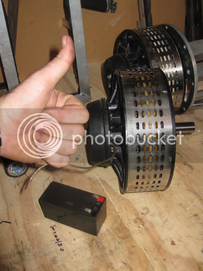
So first up, this is why I need to maintain my motor: I bent the shaft
This seems impressive, but if like any budding TTX-GP entrant you have decided to pair up two motors but put a weak coupling between them, this might be more common than you anticipated. So the good news is the shaft can be replaced, but there are a few things you need to do to get to this stage. First up, a little bit of useful info on the Agni motor - it is a single load-bearing shaft with only a dual bearing behind the front face to hold everything in place and bear the load. The motor is literally held together by the strength of the magnets! So much of the technique revolves around not getting your fingers jammed in the magnets.
First up, vacuum the shed / workshop and make sure it's plenty clean. Magnets attract iron filings, and any copper or aluminium can cause potential shorts.
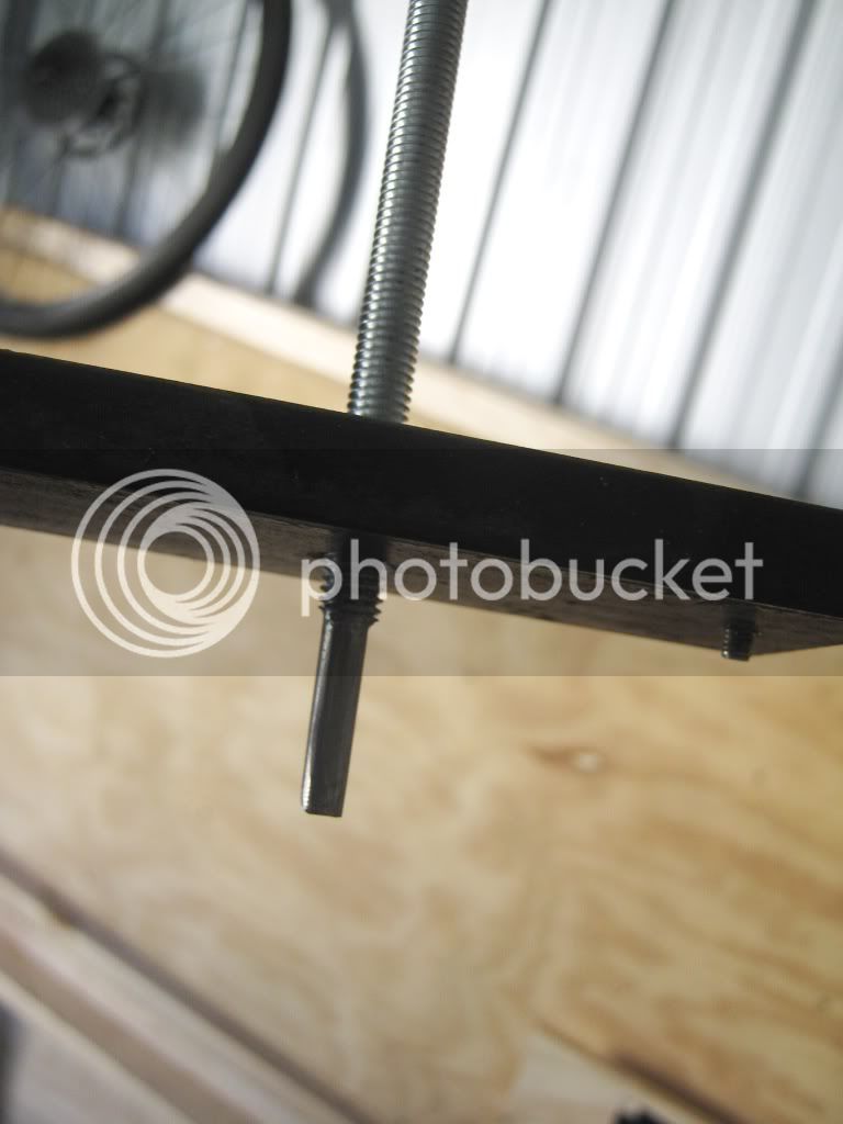
Now, you will need a long, good quality 6 mm Allen key, 13 mm ring-spanner (wrench for those north Americans), Phillips head and normal screwdriver and a bench vice with bits of wood to protect the shaft from damage. You will also need to fabricate a case splitter from a piece of 10 x 20 mm thick steel, at least 100 mm long. Punch mark and drill three holes in a straight line, 49 mm apart, with the centre hole being 6.8 mm in diameter. The closest you can get to this in imperial is 17/64ths, which is a little tight for my liking. Now, thread this hole with an M8 x 1.25 tap with lots of machine oil. The outer two holes can be drilled half way with the same 6.8 mm drill bit, but finish the last 3 mm with a 4.5 mm drill bit for the M4 screws. The 0.5 mm allows for any sloppiness") Now take about 200 mm of M8 x1.25 threaded rod and file the last 20 mm down to a point about 6 mm in diameter. This will sit inside the recess of an Allen screw and provide pressure, so make sure it's no bigger!
Now take about 200 mm of M8 x1.25 threaded rod and file the last 20 mm down to a point about 6 mm in diameter. This will sit inside the recess of an Allen screw and provide pressure, so make sure it's no bigger!
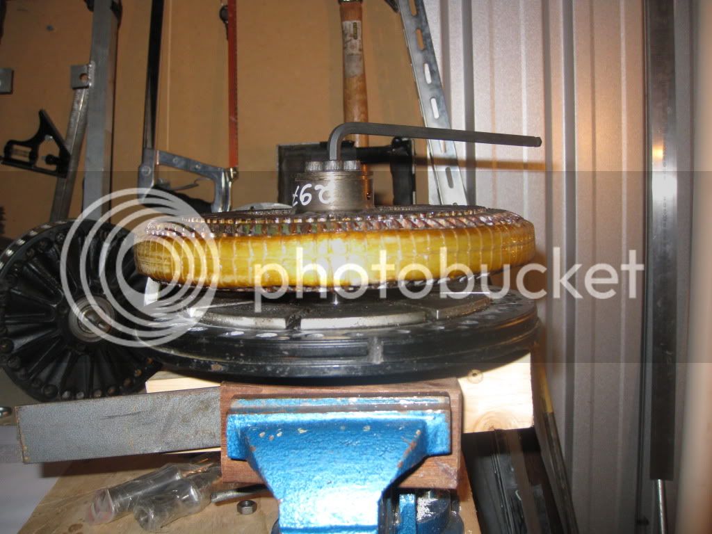
Start by first removing the brush housing of the motor. If the alignment marks aren't obvious, make your own so that you can put them back on with the right amount of advance / retard. Now unscrew the four outer screws with a Phillips head driver. As you undo the last screw the whole lot will pop out as the brushes are under pressure from the springs. Gently lift them away without doing any damage to the brushes.
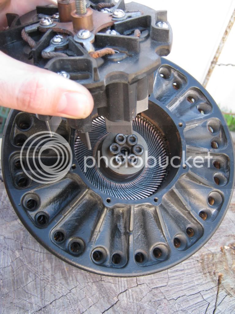
Put these in a safe spot away from crap and dust.
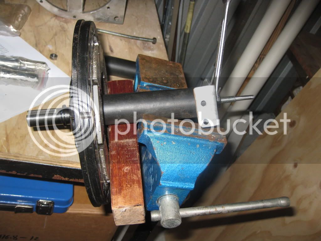
Now screw the plate onto the motor (sans brush holder) with two M4 screws.
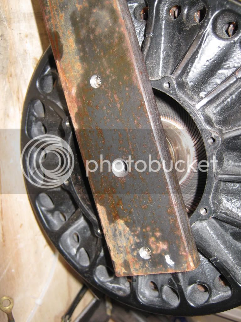
Insert the threaded rod, pointy bit first, and screw it in.
Wind two nuts down to about 40 mm above the plate and lock tighten them. Now, take the 13 mm ring spanner and wind clockwise to drive the rod into the motor. This will begin to tighten. As you wind the rod in, the case will split. Only the force of the magnets are doing this!
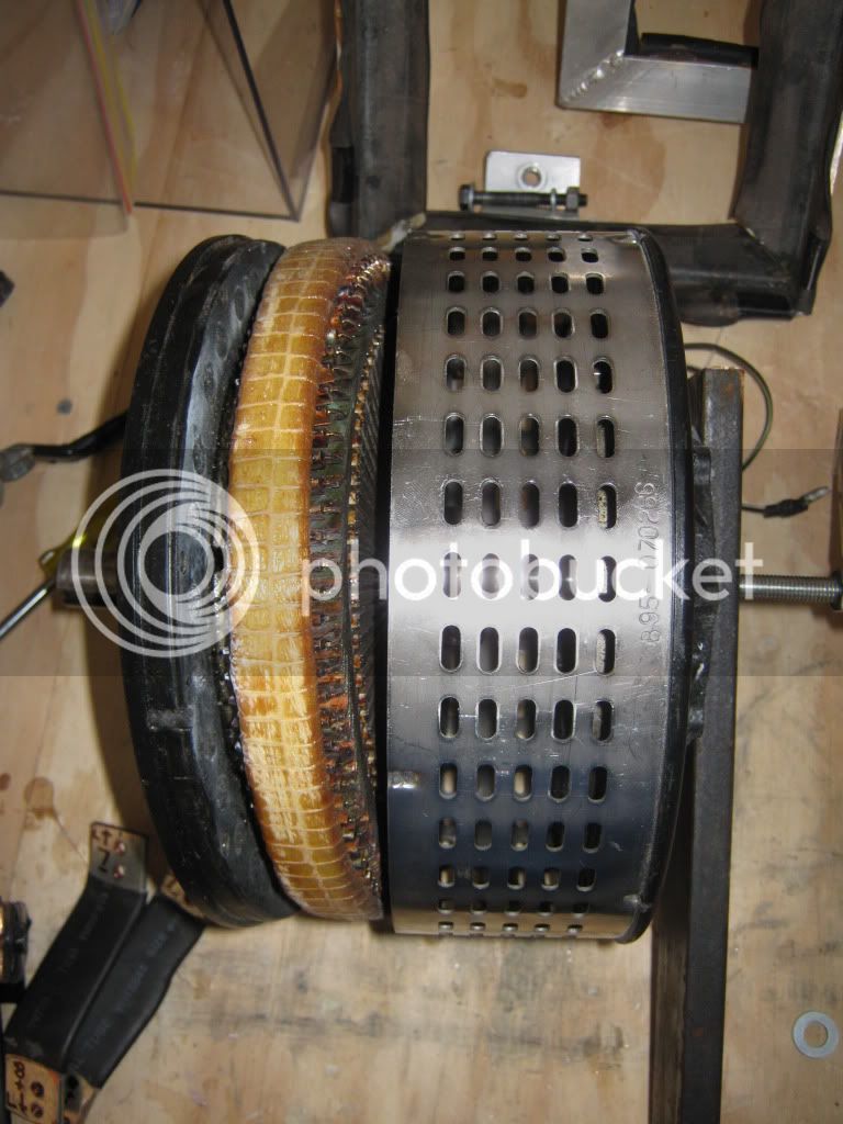
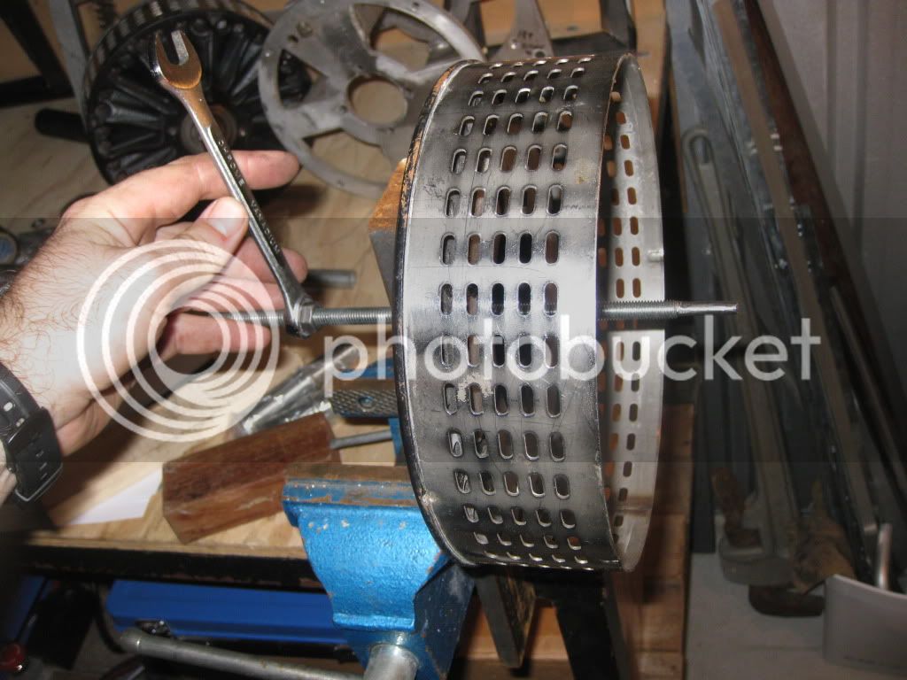
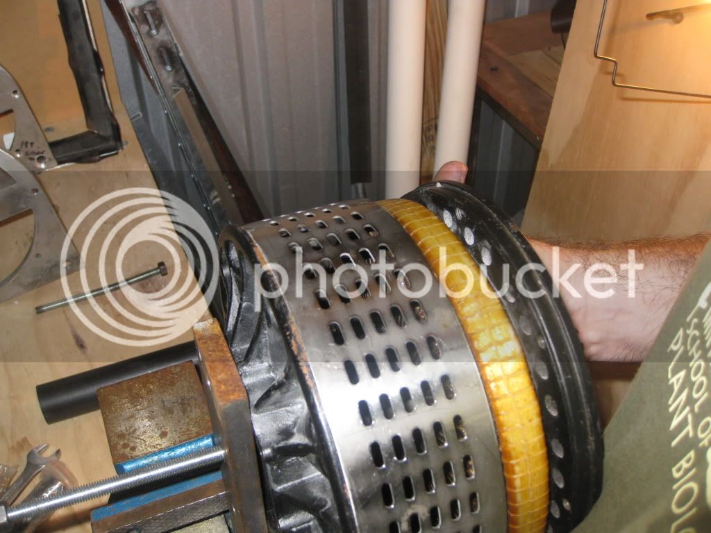
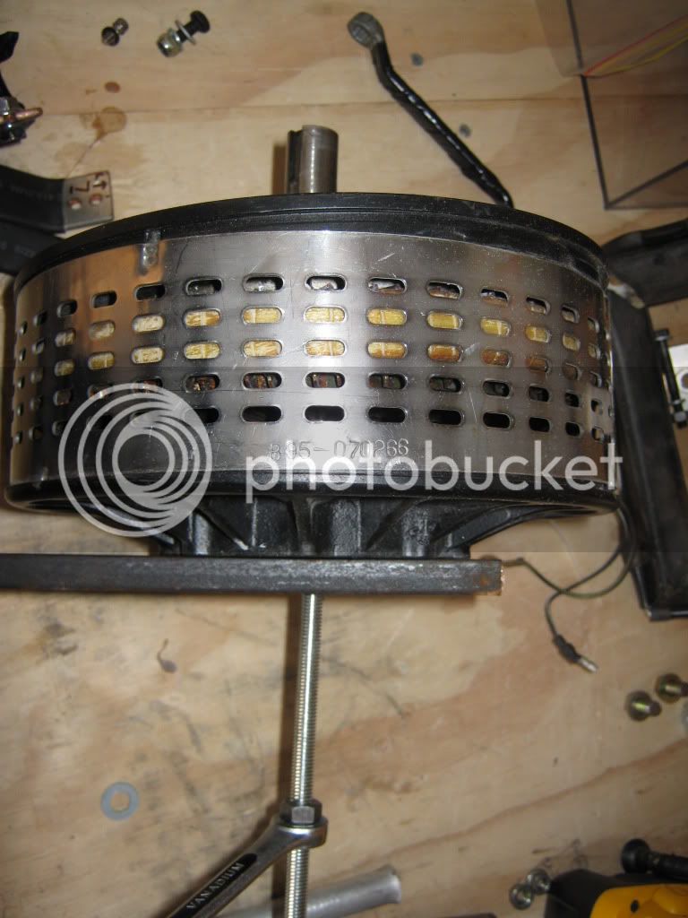
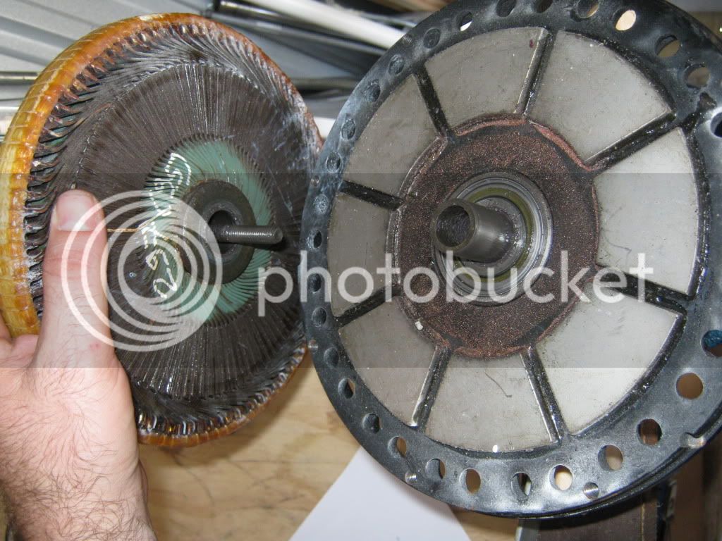
It will begin to tip to one side - don't be tempted to put your fingers in there to pull it apart yet! Keep winding until the entire armature is outside the stainless steel retainer. Then you can pull it off.
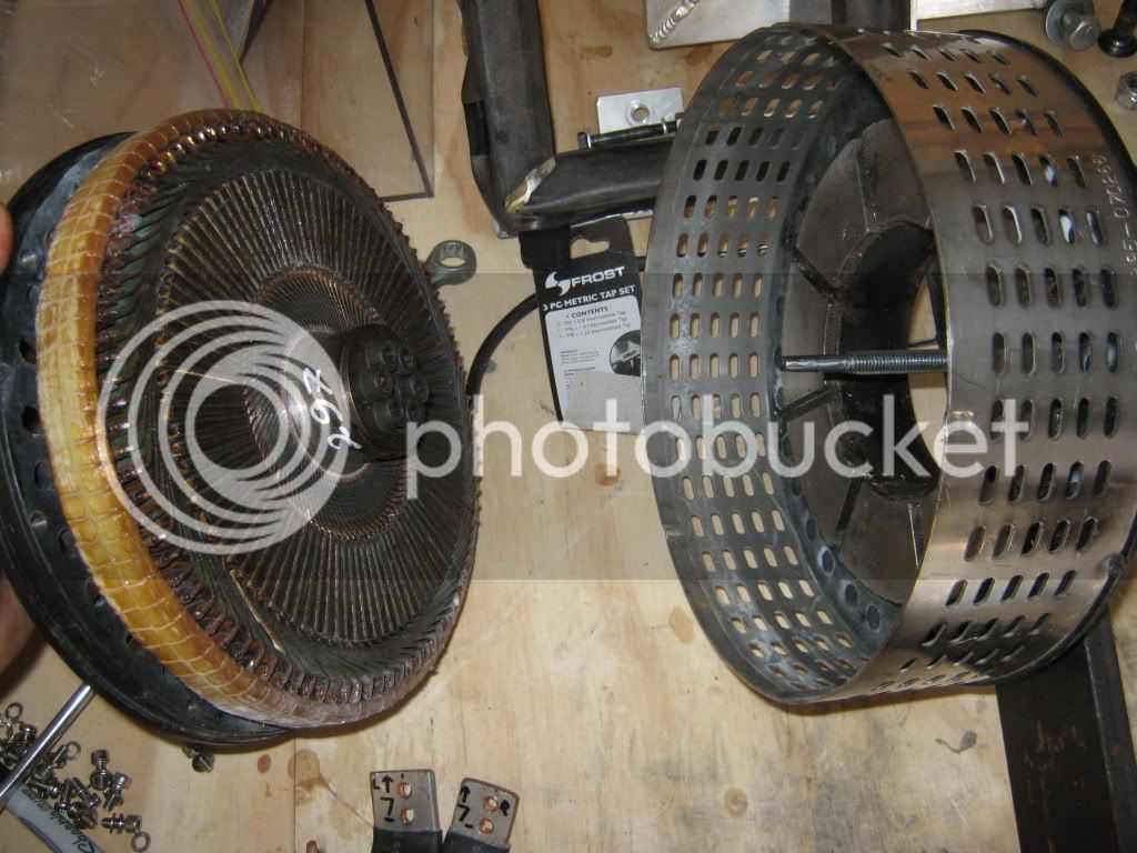
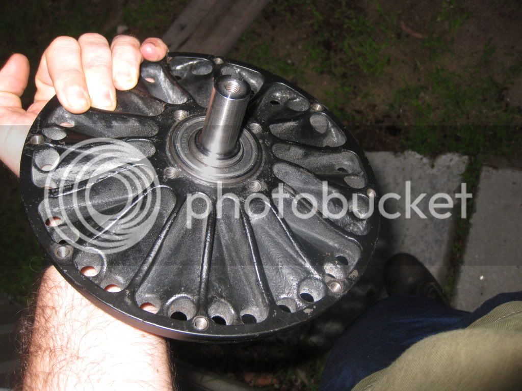
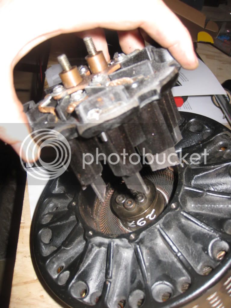
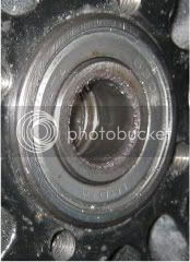
This is what the inside of the back of the motor looks like:
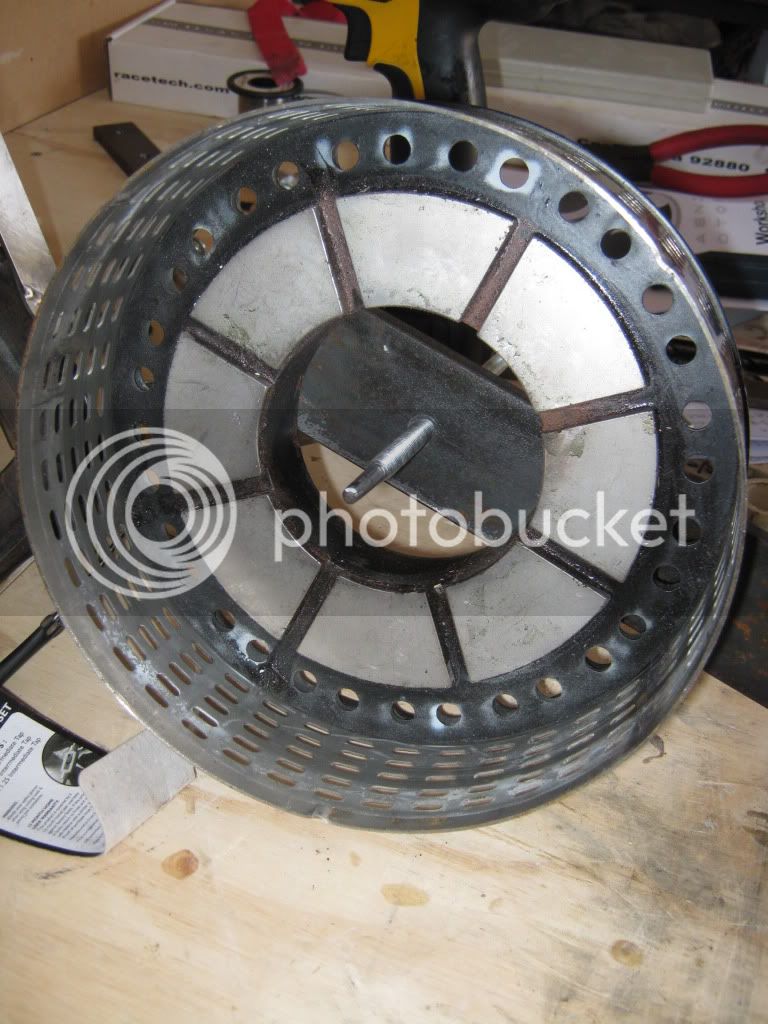
Now, place the rear half somewhere away from ferromagnetic metals!
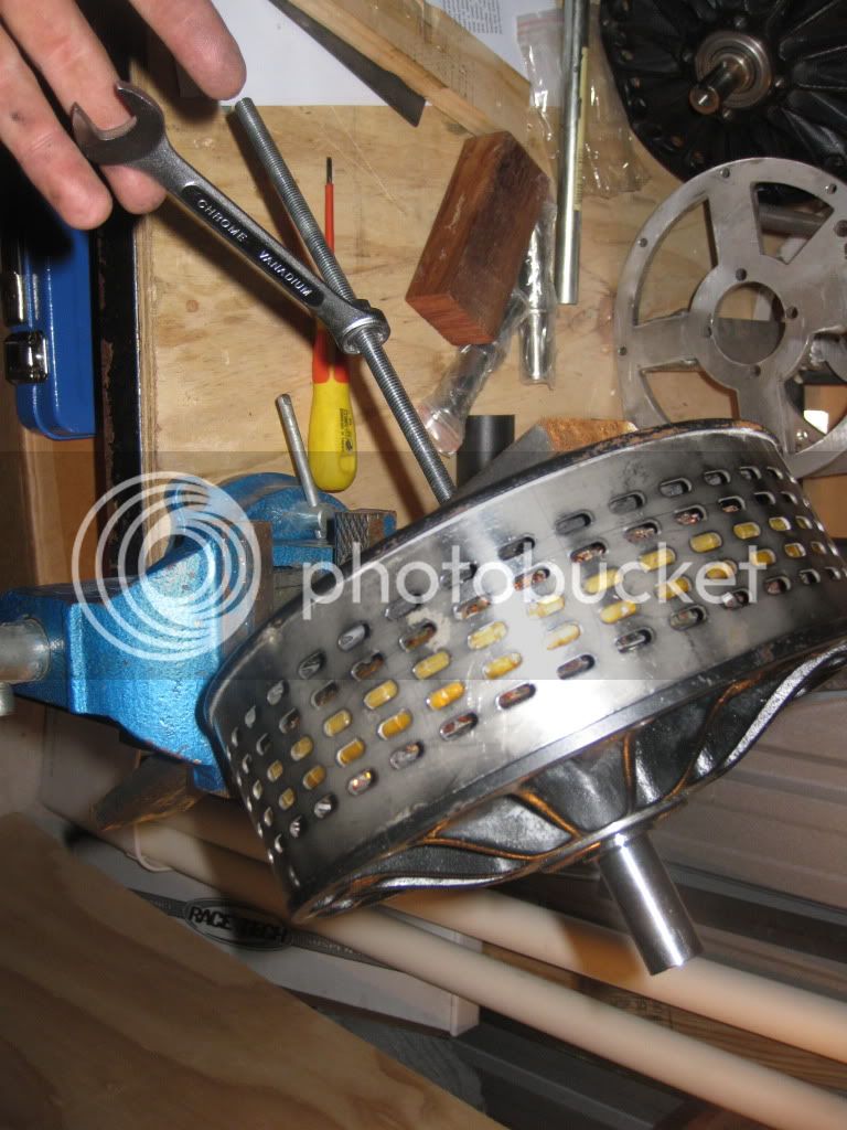
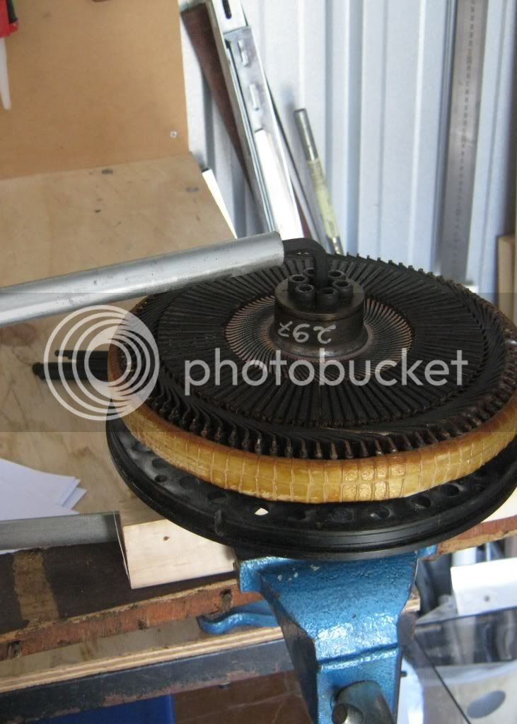
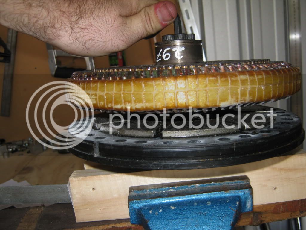
OK, to remove the armature from the front half. Place it in a vice with wood to protect the shaft (if the shaft is bent to buggery, who gives a sh1t, but if you want to do something other than change a shaft, look after it). Tighten the vice as hard as you can, making sure the keyway is facing away from the vice. The next step requires a lot of radial force, so slide a bit of flat 15 x 3 mm steel into the keyway to provide some additional resistance while turning. Secure the 6 mm Allen key into the centre bolt of the armature. Don't undo the outer 6. It will be loose for a bit, then get tight - really tight. Slide some steel tubing over the Allen key and really wail on it.
The armature will begin to lift off to the point where the bolt becomes loose and you can wriggle the whole lot off.
Check it for any obvious damage etc.
Now place the front case between two bits of wood in the vice. Don't crush the magnets!
Screw a piece of 135 mm long M8 x 1.25 threaded rod into the shaft like so:
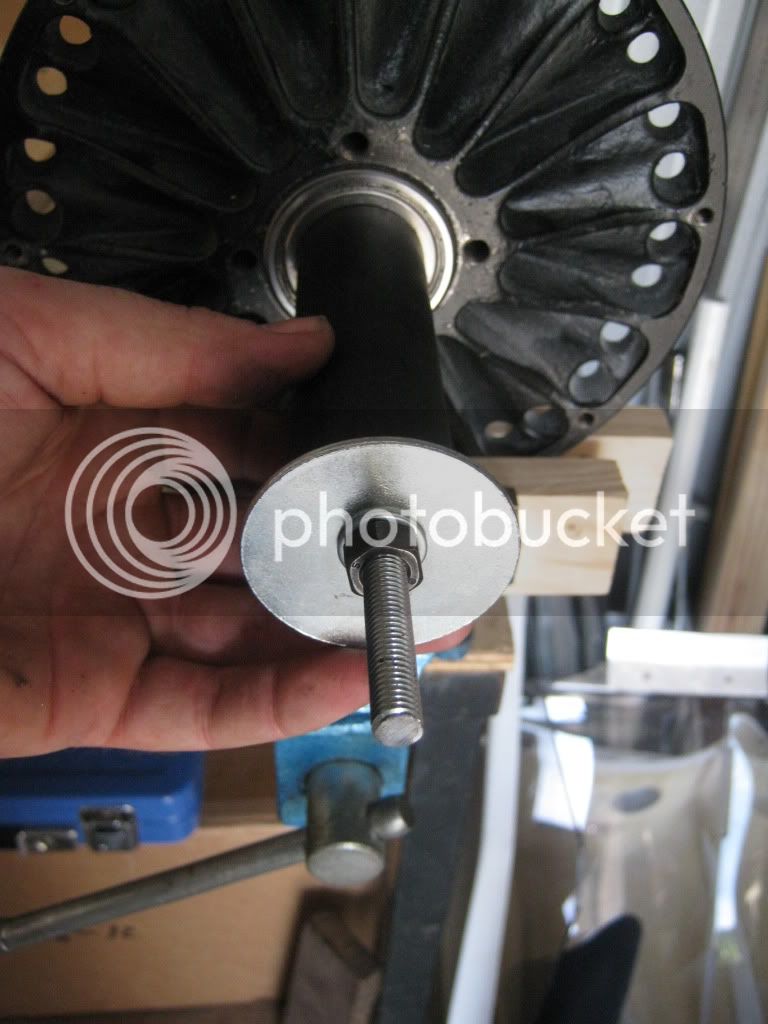
Then slide a piece of 25 mm INSIDE diameter steel tubing over the shaft. It needs to be a bit shorter than the combined length of the rod and the shaft; so about 120 mm long. Place a couple of big washer with a small hole (well, enough to clear the M8 rod) over the end of the rod, with any additional washers which might help prevent it from pulling through. While in the vice, tighten it up so that it is snug and begins to turn the whole shaft.
Now, put the whole lot in the vice and tighten on the bit of pipe nice and tight.
Now tighten the nut, using any leverage as necessary. I found the old fork stanchions from my RG250 to be perfect
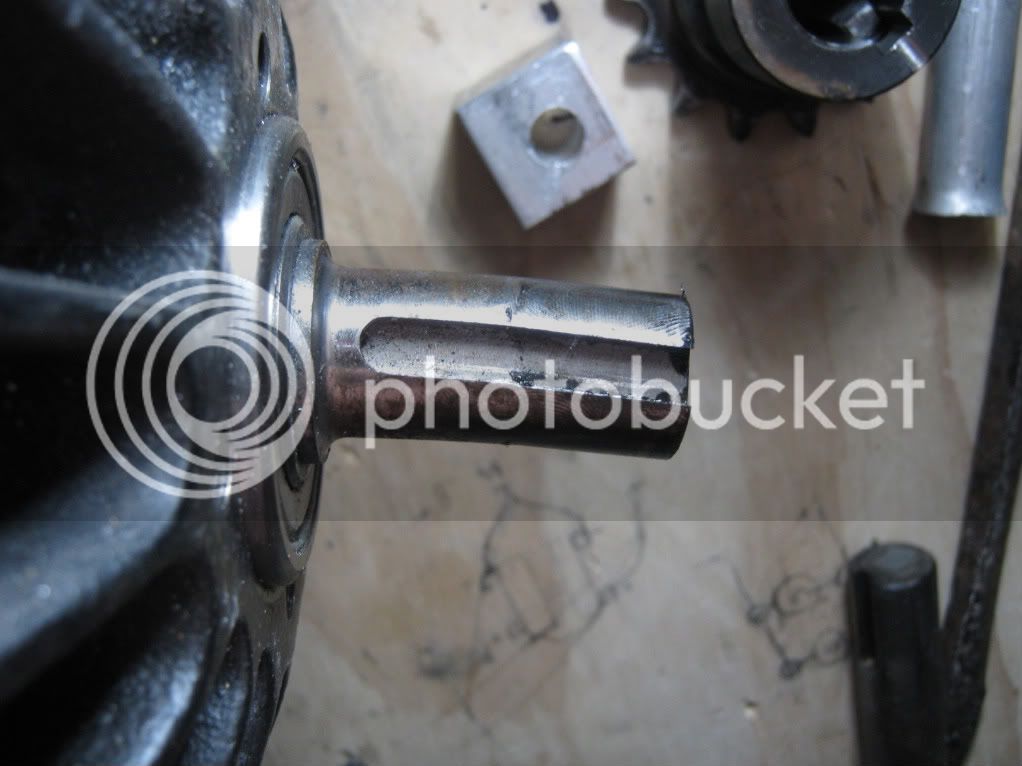
Eventually the shaft will slide out of the bearings in the the front half of the case.
And now we have removed the bent shaft!
At this stage you can remove the bearings by tapping them out with a bit of 10 mm rod, tapping the inside bearing out and then the outer bearing out (in opposite directions, as there is a retainer between the two).
If like me you need to replace the shaft and the bearings are OK, then place the new shaft in the bearings from the outside. Don't hammer on it to set it in place, rather, pull it back in from the inside using the same threaded rod and a slightly shorter bit of 25 mm ID pipe. Pictures of the replacement process to come soon!!
Cheers,
CHRIS
Maintenance of an Agni 95B permanent magnet motor.
So after trying to make sense of the Agni workshop manual I decided the world would be better off if I just documented my maintenance in photos and give some advice.
So first up, this is why I need to maintain my motor: I bent the shaft
This seems impressive, but if like any budding TTX-GP entrant you have decided to pair up two motors but put a weak coupling between them, this might be more common than you anticipated. So the good news is the shaft can be replaced, but there are a few things you need to do to get to this stage. First up, a little bit of useful info on the Agni motor - it is a single load-bearing shaft with only a dual bearing behind the front face to hold everything in place and bear the load. The motor is literally held together by the strength of the magnets! So much of the technique revolves around not getting your fingers jammed in the magnets.
First up, vacuum the shed / workshop and make sure it's plenty clean. Magnets attract iron filings, and any copper or aluminium can cause potential shorts.
Now, you will need a long, good quality 6 mm Allen key, 13 mm ring-spanner (wrench for those north Americans), Phillips head and normal screwdriver and a bench vice with bits of wood to protect the shaft from damage. You will also need to fabricate a case splitter from a piece of 10 x 20 mm thick steel, at least 100 mm long. Punch mark and drill three holes in a straight line, 49 mm apart, with the centre hole being 6.8 mm in diameter. The closest you can get to this in imperial is 17/64ths, which is a little tight for my liking. Now, thread this hole with an M8 x 1.25 tap with lots of machine oil. The outer two holes can be drilled half way with the same 6.8 mm drill bit, but finish the last 3 mm with a 4.5 mm drill bit for the M4 screws. The 0.5 mm allows for any sloppiness
Now take about 200 mm of M8 x1.25 threaded rod and file the last 20 mm down to a point about 6 mm in diameter. This will sit inside the recess of an Allen screw and provide pressure, so make sure it's no bigger!
Start by first removing the brush housing of the motor. If the alignment marks aren't obvious, make your own so that you can put them back on with the right amount of advance / retard. Now unscrew the four outer screws with a Phillips head driver. As you undo the last screw the whole lot will pop out as the brushes are under pressure from the springs. Gently lift them away without doing any damage to the brushes.
Put these in a safe spot away from crap and dust.
Now screw the plate onto the motor (sans brush holder) with two M4 screws.
Insert the threaded rod, pointy bit first, and screw it in.
Wind two nuts down to about 40 mm above the plate and lock tighten them. Now, take the 13 mm ring spanner and wind clockwise to drive the rod into the motor. This will begin to tighten. As you wind the rod in, the case will split. Only the force of the magnets are doing this!
It will begin to tip to one side - don't be tempted to put your fingers in there to pull it apart yet! Keep winding until the entire armature is outside the stainless steel retainer. Then you can pull it off.
This is what the inside of the back of the motor looks like:
Now, place the rear half somewhere away from ferromagnetic metals!
OK, to remove the armature from the front half. Place it in a vice with wood to protect the shaft (if the shaft is bent to buggery, who gives a sh1t, but if you want to do something other than change a shaft, look after it). Tighten the vice as hard as you can, making sure the keyway is facing away from the vice. The next step requires a lot of radial force, so slide a bit of flat 15 x 3 mm steel into the keyway to provide some additional resistance while turning. Secure the 6 mm Allen key into the centre bolt of the armature. Don't undo the outer 6. It will be loose for a bit, then get tight - really tight. Slide some steel tubing over the Allen key and really wail on it.
The armature will begin to lift off to the point where the bolt becomes loose and you can wriggle the whole lot off.
Check it for any obvious damage etc.
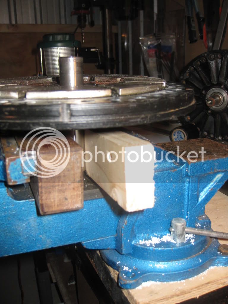
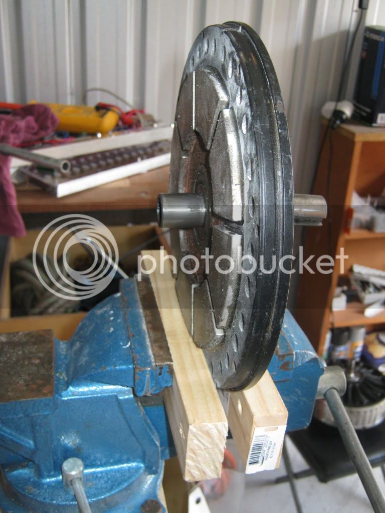
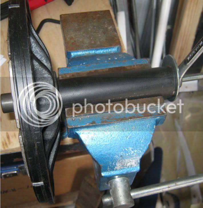
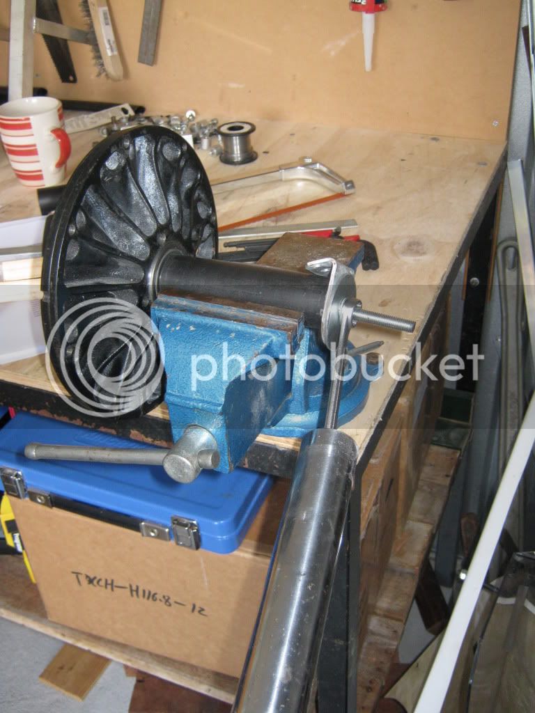
Now place the front case between two bits of wood in the vice. Don't crush the magnets!
Screw a piece of 135 mm long M8 x 1.25 threaded rod into the shaft like so:
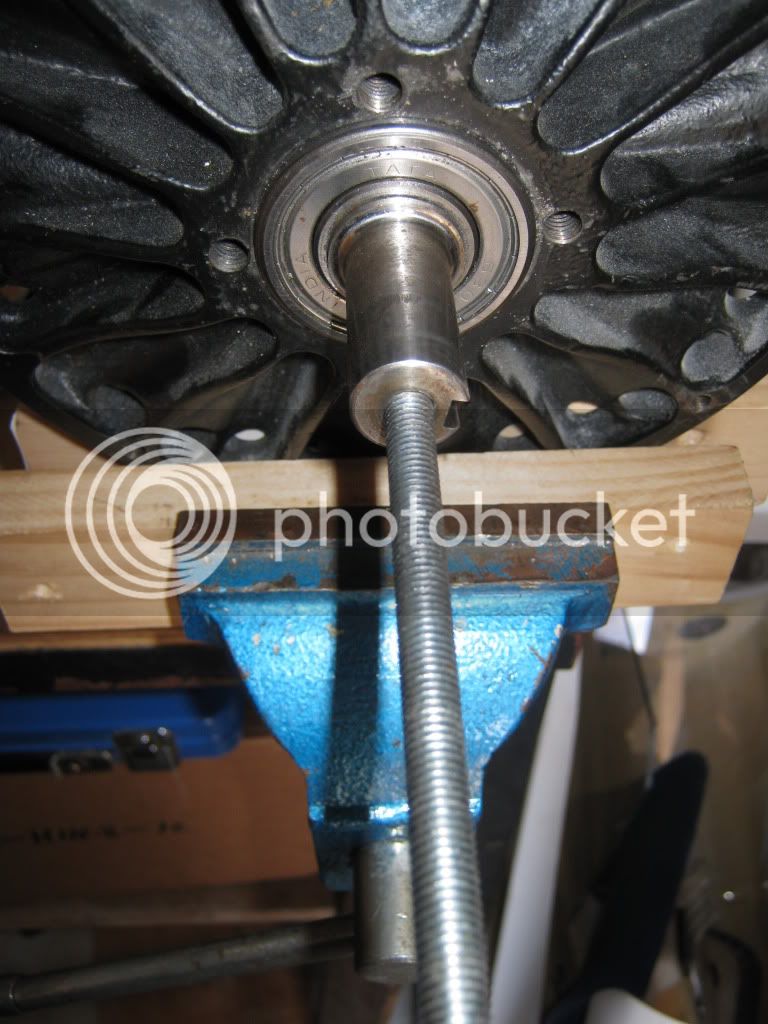
Then slide a piece of 25 mm INSIDE diameter steel tubing over the shaft. It needs to be a bit shorter than the combined length of the rod and the shaft; so about 120 mm long. Place a couple of big washer with a small hole (well, enough to clear the M8 rod) over the end of the rod, with any additional washers which might help prevent it from pulling through. While in the vice, tighten it up so that it is snug and begins to turn the whole shaft.
Now, put the whole lot in the vice and tighten on the bit of pipe nice and tight.
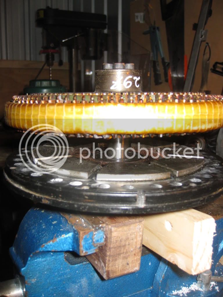
Now tighten the nut, using any leverage as necessary. I found the old fork stanchions from my RG250 to be perfect
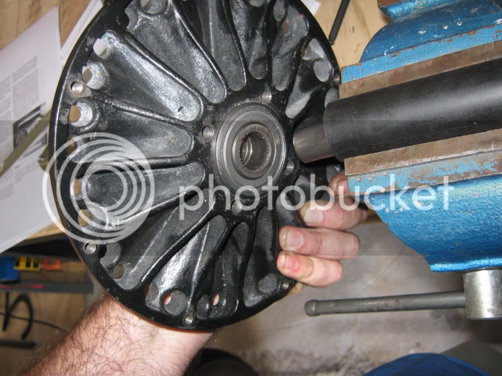
Eventually the shaft will slide out of the bearings in the the front half of the case.
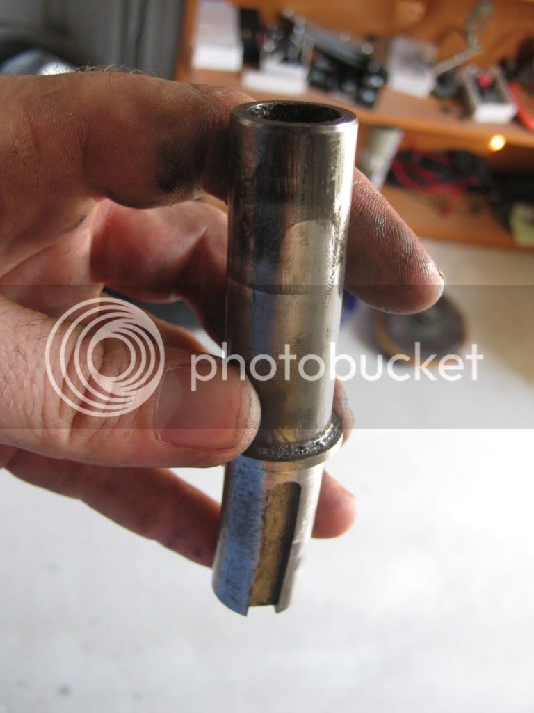
And now we have removed the bent shaft!
At this stage you can remove the bearings by tapping them out with a bit of 10 mm rod, tapping the inside bearing out and then the outer bearing out (in opposite directions, as there is a retainer between the two).
If like me you need to replace the shaft and the bearings are OK, then place the new shaft in the bearings from the outside. Don't hammer on it to set it in place, rather, pull it back in from the inside using the same threaded rod and a slightly shorter bit of 25 mm ID pipe. Pictures of the replacement process to come soon!!
Cheers,
CHRIS