Alternator Hall Sensor Positioning

tugs26

1 µW
Joined
Jan 29, 2019
Messages
3
Hey Guys!

I’ve converted a car alternator to be a BLDC. I can confirm that it works fine with a sensorless speed controller. I recently purchased a sensored speed controller, as well as three hall sensors.

I’ve followed the appropriate mathematical formula for hall sensor placement in a BLDC motor, and mounted the sensors accordingly. But the speed controller, after doing a startup test where it turns the motor a little, indicates that there is an issue with the hall sensors.

So my question is, where do I need to place those hall sensors? My gut tells me that hall sensors must be placed differently in an alternator-BLDC to a normal BLDC, due to having a field coil in the rotor, and the claw-shaped nature of the rotor.

Any help would be awesome! Thanks!

Controller: KEB48300X
Hall Sensors: Honeywell SS41
Alternator: 12v, 110A

fa0e973ef9e7a6b2d257e6b2d2744368.jpg
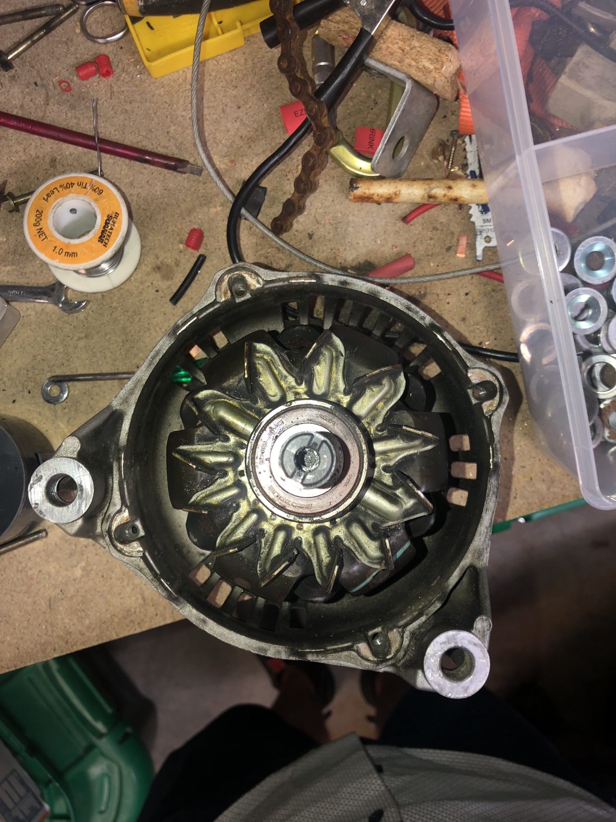
View attachment 2View attachment 1


Sent from my iPhone using Tapatalk
 
It probably needs to be in the middle of the slot, but not enough room there. You can probably set them at the edge of the stator where there is room, but you need to find the position.

One trick is to power any pair of phase wires with a limited DC current, around 2-5A and also power the field coil. The rotor will lock up in a position. This is exactly where one of the hall sensors should be on the edge of triggering. Swap phase wires and can find the other positions. You can jiggle the rotor to set the hall right where it toggles high/low.

I would suggest just running sensorless only if possible.
 
Thanks fechter, I’ll give that method a shot!


Sent from my iPhone using Tapatalk
 
tugs26 said:
Thanks fechter, I’ll give that method a shot!

How many volts are you activating the field windings with?

Also I dunno if this link helps you.
http://e-zephyr.blogspot.com/2016/09/alternator-to-motor-conversion-for.html

useless vid
https://youtu.be/b46AMgER8FY?t=10

but this maybe helpful, I copied the timestamp
https://youtu.be/iGoODvwNbQU?t=72

Can you post up more pictures?
I have an alternator ready for this kind of project, just recieved my sensorless/sensored controller yesterday!
 
The output range of the controller is 24-48v, but I haven’t tested what it’s actually putting out... I can do that if you need a precise figure :)


Sent from my iPhone using Tapatalk
 
tugs26 said:
The output range of the controller is 24-48v, but I haven’t tested what it’s actually putting out... I can do that if you need a precise figure :)


Sent from my iPhone using Tapatalk

I meant the brush voltage on sensorless.
 
Here's my findings with driving on alternator. If you use without sensors, to generate back emf, rotor need min 1.8A. I'm using pwm for rotor, and testing with dc source gave me the same amps.
I installed sensors, but maybe made a mistake for placing them, because, controller work same with or without them and hall sends info.
If current for rotor is below ~1.8A, you can achieve higher rpm's, but risk getting alt drop out of sinc with controller.
 
Bane66 said:
Here's my findings with driving on alternator. If you use without sensors, to generate back emf, rotor need min 1.8A. I'm using pwm for rotor, and testing with dc source gave me the same amps.
I installed sensors, but maybe made a mistake for placing them, because, controller work same with or without them and hall sends info.
If current for rotor is below ~1.8A, you can achieve higher rpm's, but risk getting alt drop out of sinc with controller.

Hey ^^
Nice to see that you returned to the thread and talk about your results

I recommend you to see Austiwawa's new video about alternators being converted to motors, he also had problems with hall sensor placement:
[youtube]rQy-hIMY__A[/youtube]

And also recommend you to see Enrengineering's playlist on the CAGK project (Car Alternator-powered Go-Kart), because he also used hall sensors to get a programmable controller:
https://youtube.com/playlist?list=PL8wB0836213vIgADVHJPvOD1L1mmdVpu3
 
monette999 said:
Do you have a picture how to place the hall sensors?

Not all alternators are made equally, so a single photo won't be a correct way to help you.
Austiwawa's video have a quick equation that you can use to know where to install the hall sensors
 
I'm currently waiting for the lockdown to end and also finish my exams, chances are that I'm going to revisit the CAGK project, because after watching Austiwawa's video I didn't placed the sensors at the middle of the stator coils, I placed them just at the edge. And also check/verify that I have the sensors positioned properly.
I'm happy to see that the videos I made are inspiring other people to build their own EV's.
 
Back
Top