analog bldc zero cross detector

dirty_d

10 kW
Joined
Jun 16, 2007
Messages
985
Location
Massachusetts
i found this in an ATmel application note for sensorless bldc motor control. when i make my motor controller in going to use something like this because the ADC smaple rate on the uC is too slow for a high pole count high rpm motor. at 6000rpm on a 12 pole motor the time the unpowered phase is floating is only 139 microseconds long, with 20khz pwm thats only 2.8 pwm periods long, so you need to do some sort of continuous backemf monitoring not just only during pwm on, or pwm off.

the problem i think i see with this is that when the motor isnt being commutated(unpowered), the voltage coming from the phase wires is 3-phase AC, when its being commutated the most negative leg is always connected to ground, and the most positive to VCC, so you dont have any negative voltages. but if its unpowered and the motor is spinning you will have negative voltages going to the inputs of the op-amps, the op-amp inputs are only rated for -0.3V. am i missing something here?


application note: http://www.atmel.com/dyn/resources/prod_documents/doc7658.pdf
 
oh yea, i forgot about that. ive been doing my silumations without the inverter section, just straight off a 3 phase ac voltage source.
 
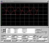
ok so with the flyback diodes the backemf waveform ends up being centered on half of the DC bus voltage right? that how it ended up in the simulation at least. i added some pwm noise in there and that circuit worked pretty good, i got a nice clean square wave out of the comparators.

i think the voltage dividers can be done away with as well, all that matters is the area where the crossing takes place, if the signals are centered on half the dc bus, if your supply was 48V, you could just put a 30V zener on each comparator input(for lm339). that should give better performance at low speed.
 
dirty_d said:
ok so with the flyback diodes the backemf waveform ends up being centered on half of the DC bus voltage right? that how it ended up in the simulation at least. i added some pwm noise in there and that circuit worked pretty good, i got a nice clean square wave out of the comparators.

i think the voltage dividers can be done away with as well, all that matters is the area where the crossing takes place, if the signals are centered on half the dc bus, if your supply was 48V, you could just put a 30V zener on each comparator input(for lm339). that should give better performance at low speed.

That's exactly what I was thinking, DirtyD! :D Why not use zeners just to protect whatever parts are used to detect the zero crossing, and avoid loosing sensitivity by dividing the voltage?

The way I was thinking of using zeners though was with the simple micro-controller ADC method, and this would help greatly with having better resolution just around the zero point. Normally if we scale, lets say a 50V maximum voltage down to 5V using resistor dividors we are 10 times less sensitive in our readings. So for a 10 bit ADC, we have only 50V/1000 = 0.05V per bit using resistor dividers. Without the divider, but using clamping zeners instead (and appropriate current limiting resistors of course) we get 5V/1000 = 0.005V .... much better!! I checked the BEMF of my golden motors hub, and a 5mV resolution around the zero crossing would make for easy start-ups for a sensorless system. It only takes a slight movement of the wheel to produce this kind of back EMF.

There's gotta be a catch though... can someone point out obvious problems with this idea?
 
wrobinson0413 said:
Hi ZapPat, the catch is that zeners are not very nice devices when you start using them in the analog world. They have pretty bad temperature characteristics that would probably give you incorrect voltage levels. Now if you are using them symmetrically, then you might get away with it. What I mean about symmetrically is that the same circuit blocks are affected the same way with temperature. I haven't looked at the circuit in detail to see what is critical and what can be tweaked. If you have simulated this circuit in pspice, just run a temperature sweep from 5C to 65C to see what effects you get by using the zeners. I am assuming that you probably won't ride your bike much below 5C unless you are a hardcore biker, and if the circuit is within the controller, you will see a pretty high ambient temperature after you have worked the controller hard. Another thing is if you have simulated it, I am guessing that you are using ideal signals. On my tutorial about sensorless methods, my motor guy was saying that the more saliency you have within the motor, the harder it is to get the simple methods to work well because the back EMF starts to really deviate form the ideal case. So, pretty much you need the real neutral point voltage to do away with the saliency effects. For you guys, it would probably take very little for you to pop the cover off the motor and find the star point if it is wound as a Y motor. You can use the same gauge wire as the halls, and wire out the neutral point to this circuit. There seems from a first glance to be a virtual neutral point being created in it, so maybe you can substitute the real one to give you lower speed commutation. Just speculating of course...I still haven't dived into the sensorless world fully to really understand all the gotchas.
Actually I don't really care about the precision of the zeners, as long as they still protect the ADC input they are connected to. So the most important thing to do is make sure their clamping voltage doesn't go up too much as they heat or cool (tempco?), as to not clamp the overvoltage well enough anymore. Since the zener clamp might start affecting the signal around 3.5 to 5 Volts depending on what zener we choose, and we are looking for events closer to zero volts, I would think this might work. I do wonder about the neutral point reconstruction though, and wonder if the zener could be made to work with a "virtual" neutral point - or use your idea of taking one extra wire out from the hub motor's star center point. I am not great with signal conditioning circuits and have trouble visualising on how to use them to shift voltages up and down equally in a three phase configuration, such as in DirtyD's comparator circuit.

So it seems like most brushless motor problems turn out to be hall-related, but personnaly I don't think it's really problems with hall sensors aging or such, but more of bad manufacturing and/or design of how they are mounted and protected that is the problem.
Also, you mentioned (in another thread) that the hysterisis effect in the halls will make your timing worse as your motor gets into higher RPMs, but I don't think it would be any worse than the effects of your fixed ADC sampling rate, or fixed comparator delay for that matter. Hey, even a 20kHz PWM frequency can start to look pretty darn slow if you have a high RPM/pole count motor... but this is not the case in a brushless bicycle hub. Even sensorless techniques will have more and more error, since they try to predict the next switching event 60 degrees in the future by relying on the measured time(s) it took to travel 60 degrees previously.

If one would want to drive high RPM motors, a higher switching frequency would be necessary with either sensorless or hall based methods. This might be usefull for RC motors I guess, but not usefull for hub motors.


ZapPat said:
dirty_d said:
ok so with the flyback diodes the backemf waveform ends up being centered on half of the DC bus voltage right? that how it ended up in the simulation at least. i added some pwm noise in there and that circuit worked pretty good, i got a nice clean square wave out of the comparators.

i think the voltage dividers can be done away with as well, all that matters is the area where the crossing takes place, if the signals are centered on half the dc bus, if your supply was 48V, you could just put a 30V zener on each comparator input(for lm339). that should give better performance at low speed.
That's exactly what I was thinking, DirtyD! :D Why not use zeners just to protect whatever parts are used to detect the zero crossing, and avoid loosing sensitivity by dividing the voltage?

The way I was thinking of using zeners though was with the simple micro-controller ADC method, and this would help greatly with having better resolution just around the zero point. Normally if we scale, lets say a 50V maximum voltage down to 5V using resistor dividors we are 10 times less sensitive in our readings. So for a 10 bit ADC, we have only 50V/1000 = 0.05V per bit using resistor dividers. Without the divider, but using clamping zeners instead (and appropriate current limiting resistors of course) we get 5V/1000 = 0.005V .... much better!! I checked the BEMF of my golden motors hub, and a 5mV resolution around the zero crossing would make for easy start-ups for a sensorless system. It only takes a slight movement of the wheel to produce this kind of back EMF.

There's gotta be a catch though... can someone point out obvious problems with this idea?
 
ZapPat, actually i dont think the backemf signals are centered on ground, in my simulation with the flyback diodes the signals were centered on half of the DC bus voltage. when you add voltage dividers to the comparator inputs, the waveform gets all wacky, if you ground one leg of the motor like when that phaxse is being commutated the waveform gets really wacky. im not really sure whats going on. ill try to take some screenshots.
 
ok here are the screenshots.

whats going on here, does this seem correct?

both waveforms are with respect to ground, they are one of the comparators two inputs.
 

Attachments

  • undiv.jpg
    undiv.jpg
    37.7 KB · Views: 2,626
  • divungrounded.jpg
    divungrounded.jpg
    40 KB · Views: 2,723
  • divgrounded.jpg
    divgrounded.jpg
    40.8 KB · Views: 2,630
  • grounded.jpg
    grounded.jpg
    38.7 KB · Views: 2,624
ahh crap, i think maybe you can only sample the backemf during the on period when only applying PWM to the high side fets and keeping the low side one on for the whole commutation step. this is a big problem for high speed motors since you need to continuously sample backemf. to accurately detect the zero crossing point. if i want to do continuous sampling i think i need to PWM the high and low side fets which will add to the complexity.
 
dirty_d said:
ahh crap, i think maybe you can only sample the backemf during the on period when only applying PWM to the high side fets and keeping the low side one on for the whole commutation step. this is a big problem for high speed motors since you need to continuously sample backemf. to accurately detect the zero crossing point. if i want to do continuous sampling i think i need to PWM the high and low side fets which will add to the complexity.

From everthing I've read you can only sample the motor's BEMF while switching is Off on the other phases, not while they are conducting as this would scew your BEMF readings.

Switching both high side and low side FETs as a synchronized pair is not really difficult at all, since any specilized motor control micro has hardware peripherals just for this purpose (with complementary outputs on each phase, adjustable dead times, etc). This being said, synchronous switching and sensorless operation are not directly related, one can be used with or without the other.
 
hmm, only sampling during the off time would be ok for slow motors, but for high speed motors it wont be accurate enough, you can also sample during PWM on time, the zero crossing occurs when the voltage on the unpowered winding equals half of the DC bus voltage. hte problem is trying to sample during the off time when only the high side fets are PWMed since the low side fets stay on for the whole commutation step it screws up the backemf when its the PWM off time. it would be pretty easy to do PWM on the high and low side with two 1:3 multiplexers, but i cant find any.
 
dirty_d said:
ok here are the screenshots.

whats going on here, does this seem correct?

both waveforms are with respect to ground, they are one of the comparators two inputs.

file.php


That image is with "voltage dividers on comparator inputs, no phase leg grounded." right? Are diodes present in the system that clamp the motor phases to V+ or Ground? If so, that wave form looks right as the voltage dividers would weakly pull each phase towards ground resulting in the voltages of your 3-phase motor "rolling" on rigid ground voltage. (i.e. the traces look exactly like ones a rolling equilateral triangle would generate if trajectory of a corner or the midpoint of a side was traced)

Anywho, grounding a random phase through a whole electrical cycle isn't really something a motor controller would do anyway. I think this is what's screwing up the last two plots. Assuming that your plots are centered on your ground reference, it looks like the two non-grounded phases now want to go below ground and something in the circuit is clamping those phases to ground. Have you looked at the phase currents when grounding a random phase? I bet they get pretty spectacular for half a cycle.

Back to the circuit that from the first post. The input resistor network of that circuit does several things. First it generates the average of each of the three adjacent phase pairs. [i.e. (A + B)/2, etc via R1-2, R3-4, R5-6] If a 30 or 60 volt op-amp was used these signals could be fed directly to the non-inverting input of the op-amps with the extra phase going directly to the inverting input. [i.e. the first op-amp would get (A+B)/2 and C, the next would get (B+C)/2 and A, etc] Second the resistor network includes a symmetrical set of six voltage dividers to ground reference the phase signals and reduce the signals' voltage swing to something the op-amp used will take. Third, capacitor C1-6 form a low pass RC filter in combination with the input resistors. I'd guess this is to trap noise and keep the input signal bandwidth low enough that the op-amp can keep up.

Now theoretically detecting phase zero-crossings by comparing (A+B)/2 with C should work as long as phase C is floating. (assuming phases A and B are symmetrically wound) I.E. phases A and B can be driven HIGH or LOW or floating and the above comparison should give the right answer. In reality the system probably won't be this nice. But if the op-amp outputs are sampled synchronously with the PWM signals (say, just before any FET switches) the results 'should' be pretty good.

Marty
 
thats the problem, with a 6000rpm motor with 12 poles, the microcontroller isnt fast enough to just sample at a certain PWM time, id need to make the analog circuitry output a square wave to a pin and trigger an interrupt when the pin goes from high to low or low to high. at full speed the time each phase would be floating inbetween commutation steps is only 2.8 PWM periods long with a 20khz pwm frequency.
 
The analog circuit in your first post already outputs a square wave. Op-Amps have a very high open loop gain so with no feedback it will always be saturated.

2.8 PWM periods between commutation steps is harsh. Mainly I'd want to avoid digitally sampling the 0p-amp outputs when a FET is switching or just after, so multiple samples could be taken during a PWM period.

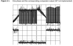
I looked at the application note from the first post. I found the figure below interesting.
One Phase Comparitor output.PNG

While the Oscilloscope screen capture has no unit labels (!@#$*%&!*@# MUST DIE!) It still shows that the op-amp circuit rejects noise quite well. In this case the signals from the Op-amps look to be valid even when the FETs are switching! In this case then a pin triggered interrupt could be used.

On the subject of speed, If Atmel doesn't have any faster parts the SX microprocessor is worth looking at. Essentially it's a fully pipelined Pic (i.e. one instruction per clock) that can be clocked at up to 75MHz. (100MHz parts were sold at one time, so some over clocking is possible too.) No hardware peripherals, but at 75MHz software can do a heck of a lot. The other micro I like is the Parallax Propeller. Provides 8x20MIPS processors and is surprisingly easy to program. It's great for me because it's most natural for me to conceive programs as cooperative tasks.

Looking forward to this,
Marty
 
dirty_d said:
thats the problem, with a 6000rpm motor with 12 poles, the microcontroller isnt fast enough to just sample at a certain PWM time, id need to make the analog circuitry output a square wave to a pin and trigger an interrupt when the pin goes from high to low or low to high. at full speed the time each phase would be floating inbetween commutation steps is only 2.8 PWM periods long with a 20khz pwm frequency.
DirtyD - Are you sure about this RPM to commutation period convertion you did here? This is what I get:

6000RPM / 60 = 100 mecanical revs per second
12 poles = 4 electrical cyles per rev
6 commutations per electrical cycle

So: 100 * 4 * 6 = 2400 commutations per second, or 416us per commutation.
This would give about 8 PWM periods per commutation - not so bad as 2.8.
Please correct me if I'm wrong, cause I did not get this from a app note or anything "official".

Also, I've been re-checking some docs about zero cross detection, and sorry but I was wrong about sampling only during off time of the PWM, it is OK to sample during on time, just sync your sampling to avoid PWM noise as you already know. Sorry for any confusion... :oops:
 
12 poles would be 6 commutation cycles per mecahnical rotation, 2 poles is one electrical cycle per mechanical revolution, there is a electrical cycle for each pole pair each mechanical revolution, there are 6 pole pairs for 12 magnets. so 100 * 6 * 6 = 3600, 1.0 / 3600 = 0.00278s per commutation step, so 278uS not 139uS, i think i divided 278 by two for some reason but that would be wrong. so thats actually 5.6 PWM periods per commutation step not 2.8. thats not enough to only sample during either on or off though the resolution would be too crappy. i think that op-amp circuit will work and just have the output trigger an interrupt, you cant PWM the only high side fets though, you have to apply the same PWM signal to the active high and low side FETs. so you either need 6 PWM outputs, or one PWM output and two 1:3 demultiplexers.
 
This is from the zero cross detection PDF where the op-amp circuit was taken:

Low pass filter introduce a delay between Zero crossing time and analog comparator output toggle.
This time must be taken into account for 30° calculation. With the above schematic the
delays generated by low pass filter is close to 125 us.

Pretty large delay compared to a 278us commutaion time... :?
 
yea but i dont think its any big deal, as long as its shorter than the commutation period you can just compensate in software. it should be a constant delay right regardless of the rpm?
 
dirty_d said:
yea but i dont think its any big deal, as long as its shorter than the commutation period you can just compensate in software. it should be a constant delay right regardless of the rpm?
True dirtyd. Also take into account the time it takes your micro to calculate the next commutation. Everything has to be done inside a 30 degree timeframe, including all compensation done in your prog.
 
Back
Top