Another 18650 stack build

LewTwo said:
....By the way in the US most of those food cans are now teflon coated (or some other unknown thin film). Also many vendors are switching to aluminum instead of steel for the base metal.
Aluminum is used for beverage ..beer, soft drink, etc and a few tuna type cans. Most food, pet food, soup cans are still steel as they use a resistance welding process to construct them. Polymer/epoxy coatings have always been used on beverage and some food cans
Sure you have to be selective if you really want to use can tinplate ( suggest paper labled bean cans, as they have no coatings inside or out) but better to seek out some of the bigger commercial containers like unused paint cans or biscuit tins.
But tin coated steel strip is a commercial product..... if you can find the outlets !
 
Finally put a full charge into the prototype battery (the arduino controlled balancer/charge controller is fully operational now) so I can do a proper discharge test over the next couple of days: I just need to wire up the cooling fan on the discharger resistor bank.
 
I experimented with Samsung 25R for something completely different and found that if I applied what I thought was moderate pressure on the top cap, the three legs attaching the positive cap to the top were deforming and several failed (three out of 40 similarly treated). LG have four legs and might resist the sort of compressive forces required to ensure good contact in your fascinating tube.
 
Thanks for the heads up James,
I must say you do have to be careful, there are 6 m6 threaded bars compressing the stack, and with nylocs on it's not easy to judge how much grief you're giving them.
I ended up tightening them all until I couldn't rotate (the whole bar c/w nuts at each end) with finger & thumb ,all the bars, then giving an extra turn each. When I decided that there were one or two no-connects, I gave an extra turn on each. I've got an 8mm layer of closed cell foam in there to act as a spring, I must say that it looks as if it is totally squashed flat...
 
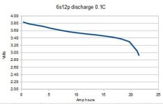
And here is the discharge curve - note this was done at an ambient temperature of about 3 to 5 C in my shed.
disch.JPG
Discharged into a 6.6ohm resistor (about 0.1C). It looks as though I should have given it quite a bit more charge (maybe charge to 4.2 or 4.3 instead of 4.0, but I'm taking it easy with it for now)
The battery should be good for 35Ah & this was 21.5Ah so I wonder whether any capacity is lost due to the low temperature
 
Cold makes a lot of difference to voltage sag. I think on my EIG cells, every 10 degrees C lower the tmeperatures is, voltage sag just about doubles.


The graph shows the discharge starts at 3.8v. If that is accurate, then if you charged to 4.0v, and it was 4.0v before applying the load, and a 0.1C load caused .2v drop, they might not be the greatest cells, and/or there may be more interconnect resistance than desired (if you are measuring at the stack interconnects and not at the cell bodies).

There will be some capacity difference between 4.0v and 4.2v; how much depends on the specific cell. On my EIG cells, 3.95v to 4.15v (their max) is something like 20%+ of their capacity.

There's also capacity difference at lower temperatures, becuase of the voltage drop.
 
Cheers AW
I reckoned at 0.1C I shouldn't be seeing a great deal of sag. The discharge end of the curve looks right (volts dropping increasingly quickly towards the end) but the "full" end of the curve looks as though I was nowhere near actually full. But I was measuring while charging and it's the cell's first full charge so I suppose there's a learning curve around how best to use my charge controller board and under what conditions cell charge is best measured. FWIW the cells are specified for 4.2V "fully charged" to 2.65V "empty". The conditions of measurement are not specified at all, I assume they mean unloaded, in which case I should set my "end of charge" detection voltage to (say) 4.3V as a matter of course. (should allow the measured discharge graph to start at 4.1V)

I suppose I could keep increasing until I start to see an increasing slope at the "full" end of the curve and note that voltage.

The cells are big name (samsung IIRC) so I'd expect them to supply the nameplate Ah if driven right.

The bottom balance stayed good at the bottom end after discharge - I must remember to check at the top end after charging :)
 
For the charging, you'd stop current, then measure, so that it's resting voltage would be the 4.2v for full.

If you test while current is flowing, you get the cell resistance and all connection resistances in there multiplied by the current for additional voltage, so you can't be certain what the voltage is, nor will it be the same offset for each cell.
 
bobc said:
I suppose I could keep increasing until I start to see an increasing slope at the "full" end of the curve and note that voltage.
......
i hope you dont mean whilst charging ? :eek:
You wont see any change in the voltage "slope" at the end of the charge curve, it will simply just level off at the max charge voltage...assuming you are using the correct CC/CV charge profile.
Just charge to the recommended max voltage, and discharge as AW says.
Read some of Drk Angels threads on "capacity mapping" if you want more detailed insight.
https://endless-sphere.com/forums/viewtopic.php?f=14&t=54202
 
Point taken; I did mean the "steeper part of the discharge curve" not "look for a steepening of the charge curve"!.
My charge controller/bottom balancer is a bit novel in that it always measures cell voltage by slapping the "balancing" discharge resistor across the cell being measured. If (this was the plan...) the balancing current is the same as the charging current, it means that as each cell is scanned during the charging process, it actually has zero current!!
Frankly I don't believe this will give the same answer as a measurement while open circuited - the cell voltage scan only zeros the current for 20ms or so, also I will charge via the battery power connections and monitor/discharge via the balancing lead. My experience is that cell voltages take quite a while to fully "settle" after currents are changed, but it's maybe a step in the right direction.
The real answer is to set up the charge controller to suit the battery and bulk charger in use,- I'm doing that process now, simultaneously looking at a new (to me) battery and a new charger controller, so it's being done incrementally (i.e. taking a while.....)
 
Back
Top