
Hi guys, been a while since I posted here! I recently built an electric skateboard using the Turnigy kit. Loved it but wanted to make use of the telemetry information available to me from the VESC and also have a more compact unit than the RC remote I was using.
I know plenty of people had already done similar to this and I could've just built one of theirs but I wanted to do my own for the learning experience.
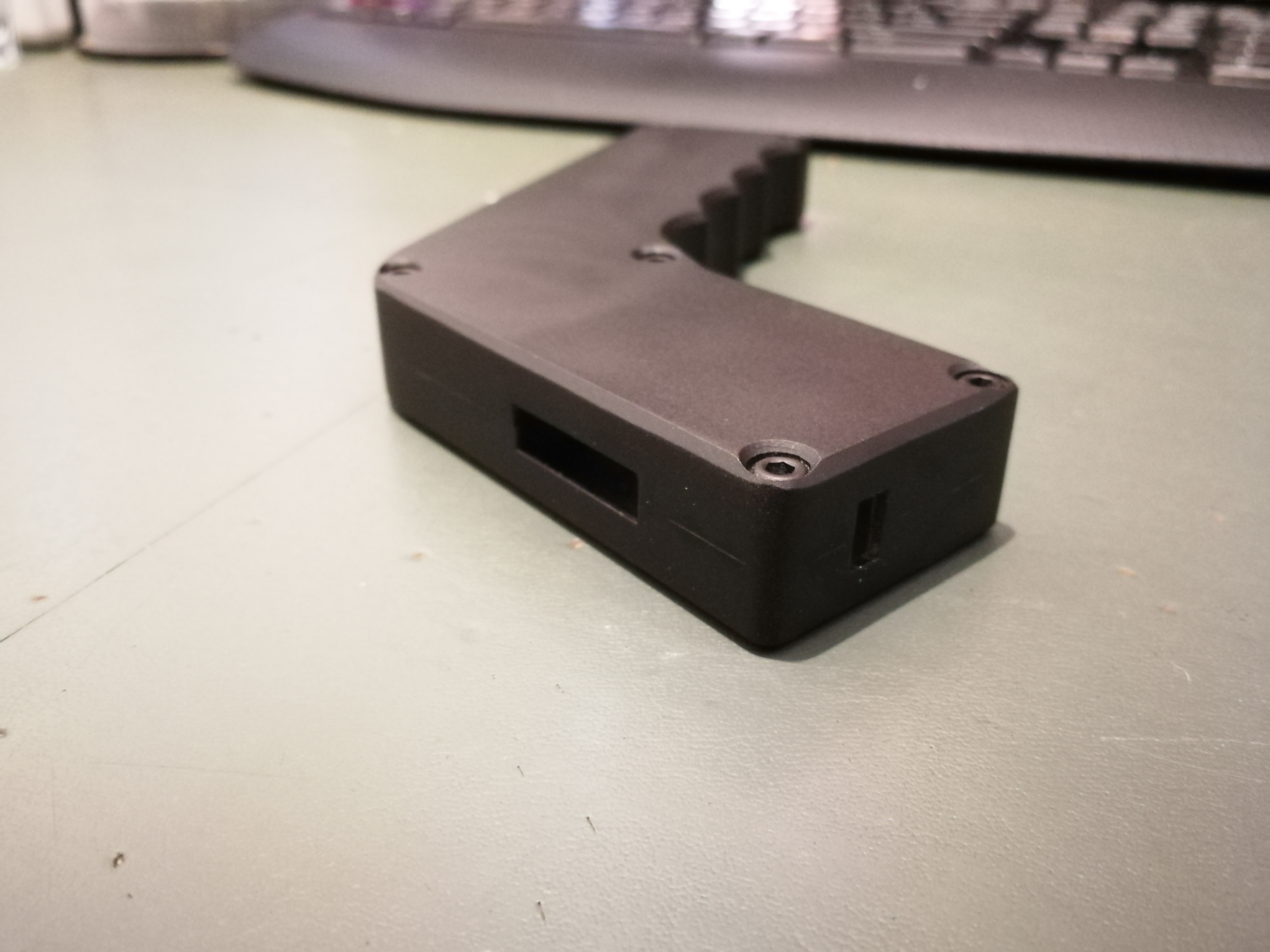
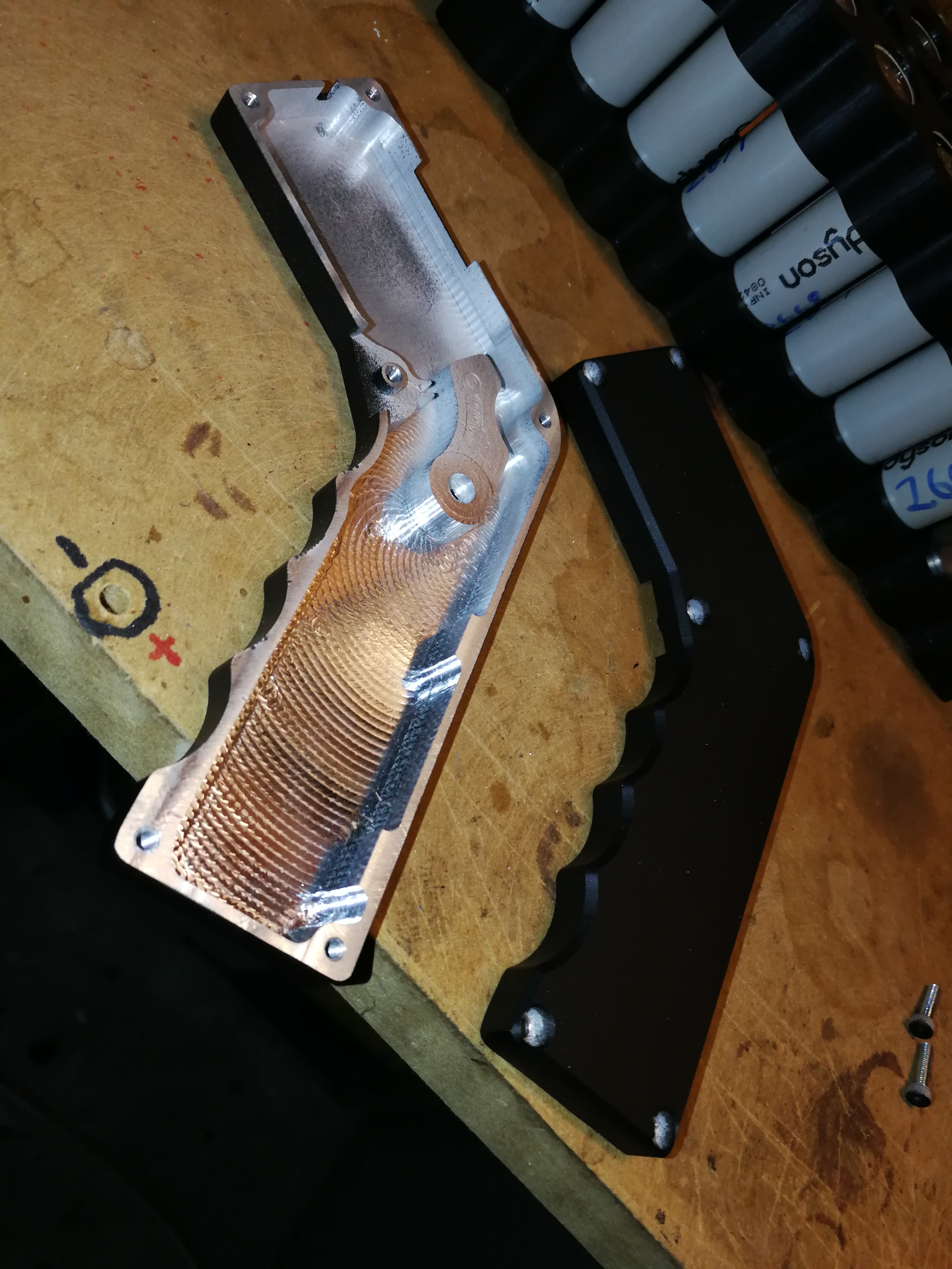
The case is made out of billet aluminium and is 20mm thick:
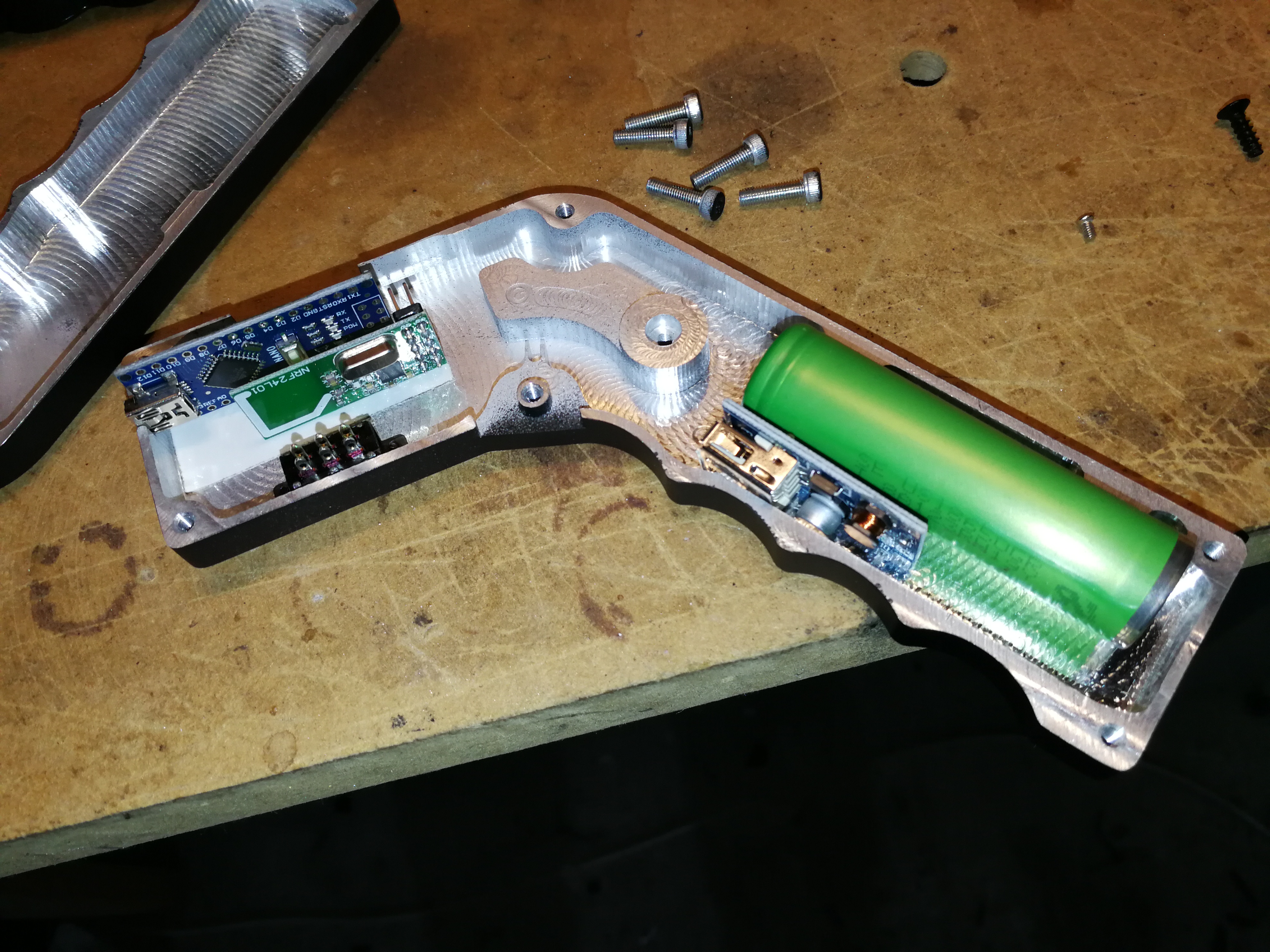
I managed to squeeze all of the electronics in, but it wasn't pretty. Will come back to this eventually and design a PCB to properly mount and connect everything. For the time being, its all wired together and held in place with hot glue. I don't have any current photos of the internals handy but here's a rough look at the layout:
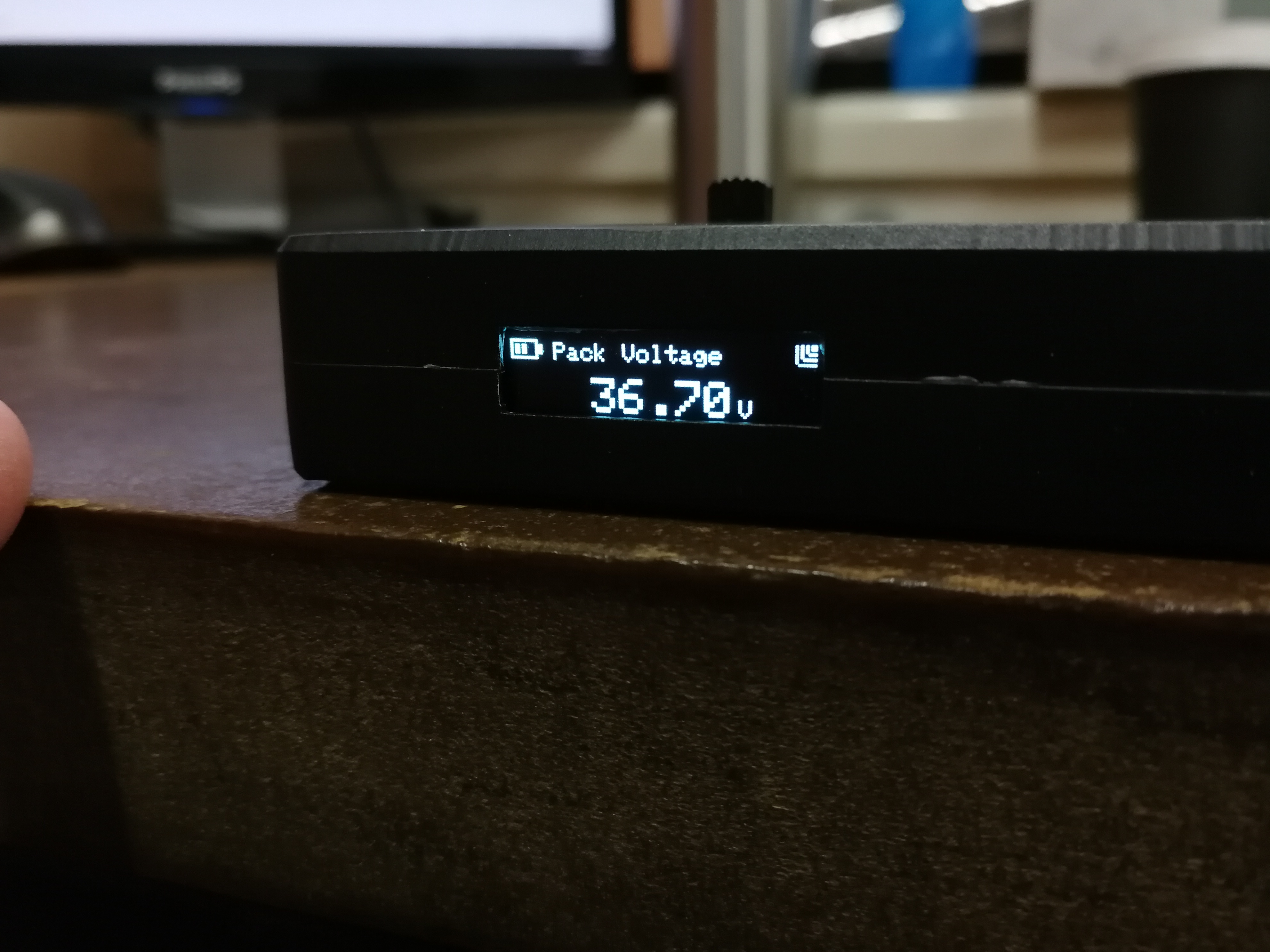
The OLED screen mounts in the slot at the top between the two halves and provides one screen of telemetry info at a time. I found any more than this on such a small screen was too difficult to read whilst moving. A single push button is used to swap between each telemetry read out (volts, amps, speed, distance, capacity).
I've got to take some pictures of the trigger but its pretty similar to most RC triggers, except I used two magenets and a hall sensor to keep the width of the housing down.
And finally, here's a picture of the RX and everything else mounted to the board, ready for testing.
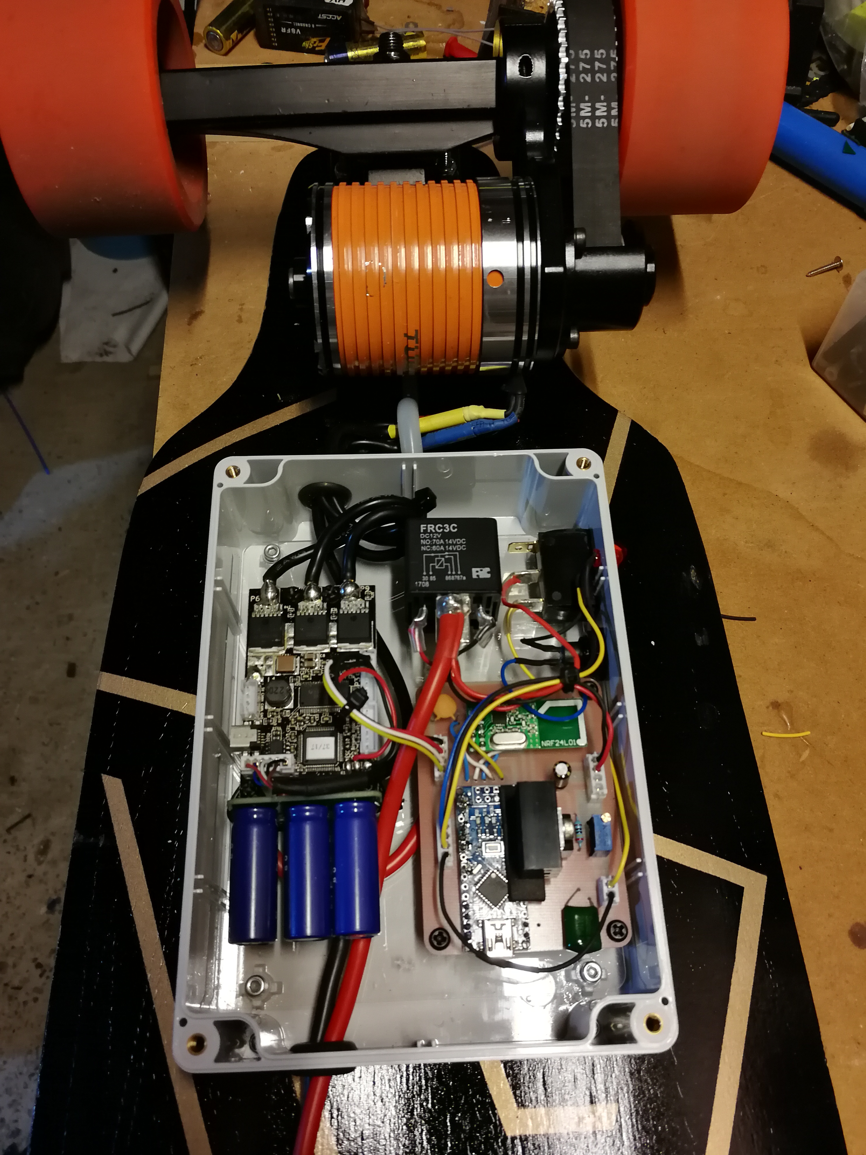
It's all working pretty well but I'm still tidying things up and making tweaks to the failsafe settings in my RX code to try and make it as safe as possible in the event the transmitter stops working.
Let me know what you think!
I know plenty of people had already done similar to this and I could've just built one of theirs but I wanted to do my own for the learning experience.
The case is made out of billet aluminium and is 20mm thick:
I managed to squeeze all of the electronics in, but it wasn't pretty. Will come back to this eventually and design a PCB to properly mount and connect everything. For the time being, its all wired together and held in place with hot glue. I don't have any current photos of the internals handy but here's a rough look at the layout:
The OLED screen mounts in the slot at the top between the two halves and provides one screen of telemetry info at a time. I found any more than this on such a small screen was too difficult to read whilst moving. A single push button is used to swap between each telemetry read out (volts, amps, speed, distance, capacity).
I've got to take some pictures of the trigger but its pretty similar to most RC triggers, except I used two magenets and a hall sensor to keep the width of the housing down.
And finally, here's a picture of the RX and everything else mounted to the board, ready for testing.
It's all working pretty well but I'm still tidying things up and making tweaks to the failsafe settings in my RX code to try and make it as safe as possible in the event the transmitter stops working.
Let me know what you think!
