Any Help on Identifying a Controller and it's Markings Code eWheels ew-19/ew-20

MTOakey

100 µW
Joined
Jun 21, 2023
Messages
9
Location
Homestead, Florida
Greetings All,
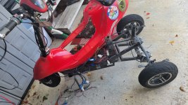
I have searched many forums and all over this one too before posting. I can not seem to find out ANY information about a Controller I took out of an eWheels ew-19 {ew-20}, and it is the original. The Company says they have "no Idea", and there is NO label on, or in, this small 500w, 63V-470uf main caps, no screws for mosfets, all printed in English on PCB controller...
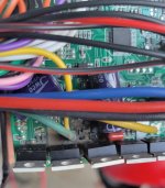
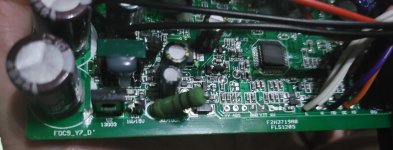
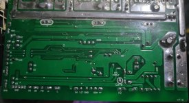
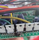
Pics show all the pertinent stuff I am wondering about, and I have removed all 9 mosfets for replacement - 6 {HY3208P} and 3 {S70N08R} - of which 1 HY was blown, 2 HY were shorted bad, and 2 S7 were also shorted. I am replacing all 9 with new HY3208P.
20230620_182312.jpg 20230620_182342.jpg
20230622_031431.jpg
20230622_031513.jpg

So, I would like to know - to the best of your all's ability - what all or most all of those points for controller wires mean/do.
Now, the obvious ones are easy, such as the Main 48vdc IN, Motor Phase, Hall sensors, Throttle, 3 speed lines, Reverse, and that is only half of the wires coming out of this thing... and there are several points available with No wire - I'd like to know what they are if possible, like Speedo pulse, reGen, Cruise ... whatever. Plus there are a bunch of other connectors wired to either "L" and Ground - or Main Red 48vdc In. ... what are they for ???

Any and All help will be greatly appreciated !!!
and eagerly awaited ...
.
 
When the FETs blew, it's possible they also took out the gate drivers. If this happened, it may be better to just replace the entire controller.
You can try measuring resistance from each FET gate leg to ground or the 12v supply and look for shorts. All the FET gates should read the same and not look shorted.

The other connection points may or may not be functional depending on the software. It will be hard to figure out what some of them do without documentation. Typically there can be features like locking functions, cruise control, etc.
Thanks for the reply...
Well, I have already removed all 9 MOSFETs, would I still check for shorts between where the legs were to both Ground or Positive ?
Because, on the board, the center pin {2} of every third of 9 mosfet shorts to Positive, and pin 3 of 1&2, 4&5, 7&8 shorts to Negative, all of those because they are connected respectively to the bus bar traces on the bottom of the pcb. Pin 1 of all 9 mosfets is not connected to anything, nor does it report any resistance or short to anywhere.

Would this mean it might be worth the $7.99 to replace all 9 mosfets and maybe have a good controller ?
If not, I'm just out the time and $7.99 ...
.
 
And by the "software" you speak of, you mean "Firmware" because it is "embedded" in chip... unless the "pin points" labeled "YY-SDA- -GND" are supposed to be for a 4-pin stand off connector for a Programming cable ??
I can make that easily enough if need be ...
The MPU/CPU chip, 12 Legs on each of the 4 sides, has the markings:
XYD32F
103C8T6
NLJ6L
1927 G
printed just like that on it.
The rest of the board and components all look good.
.
 
Pin 1 of all 9 mosfets is not connected to anything, nor does it report any resistance or short to anywhere.
One of the three pins is the gate signal. If it doesn't connect to anything then the FETs can't be driven and the controller can't work.

The two other pins are the power handling pins. For six of the FETs they will go to phases and battery rail, for three fets they will go to the other battery rail and the same phases.

Controller firmware is not generic, it's specific to the specific brand and model of unit. If it came built into a scooter/bike/etc, that FW may be custom-made for that company, too. Either way it is generally not publicly available, so you usually cant' find out anything about it (and you can't usually read it back out of the MCU chip; they tend to protect them against this).

Programming software to change settings or functions on a controller is also brand/model specific, and also generally not available.


If you've already got new FETs for it, it's worth trying the replacement...but keep in mind that *something* blew the FETs up. Usually that's an overload from a motor/controller wiring fault, often damage at the motor's cable exit. Sometimes it's a winding failure in the motor from overheating. Sometimes it was a momentary stall-current overload that the controller was not programmed to protect itself against, or doesn't have the hardware to protect against.
 
Thanks, and sometimes it's just little pudgy fingers that don't know what they are doing, fiddling around with stuff that is way beyond their pay-grade !!! {the owner of the trike - a friend} but it worked fine until it didn't, and those pins don't short to anything on the pcb, it is only a T/B board {top-bottom}, not a multi-layer.
Now, I have to figure it all out and put it back together ...
20230621_143152.jpg
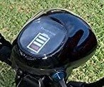
eWheels ew-19/ew-20 ... anyone got any idea about the headlight/horn/key switch unit - it has a stacking bar battery graph, and Hi beams indicator, no turn indicators? First click of keys is low beams and system On, second click is High beams and On. Built in horn sounds when the 2-wire cable for it is shorted - like for a switch. The three other wires -1 black all alone, and a yellow and an orange together in a connector are what is boggling me... yellow and orange work with the key switch click 1 & 2 respectively - but the short out to the black one... does that mean that the black wire should get 48v or do each of the other ones get the 48v and black is a ground ?????

.
 
Last edited:
I'd assume its ground but do check with a multi meter. Continuity test selection, take one lead to black wire, take other lead to the ground on the pcb and if the diode thing beeps audibly like most digital multi meters do then yes it is ground. Look for and trace the black wire and see where it goes, do the trace lines on the pcb go to something that look like a ground. Color of wire being black - Yes you cant be sure its 100% ground but it should be. Thats why you do the visual and continuity test, even an Ohms reading of zero ohms or 0.1ohms is a confirmed continuity test.
 
Thanks, but, can't check THAT because the controller is blown... so I have just those 3 wires coming out of the head display unit... the black by itself, a yellow and a orange in a connector - they do not short to the black at all, no ohmx at all... but they together DO short together for keyswitch ON/Low beams AND keyswitch ON/High beams... that switching differential is done inside the head unit itself. Both "On" positions also turn on the "Battery monitor display" which is a few horizontal bars that stack up inside the graphic of a battery... IT also has no connection diagram or instructions. The only other thing this head unit does is show a blue indicator for when the keyswitch is turned to "High beams". So, a black wire, an Orange wire and a Yellow wire that remain mind boggling to me... do the yellow and orange just "Y" together and connect to 48v and the black might be a ground ???
ONE of those three wires HAS to feed the 48v to the head or nothing THERE will work, not the horn or the lights or the battery monitor.

51fae4k0NXL._AC_.jpg
 
and those pins don't short to anything on the pcb, it is only a T/B board {top-bottom}, not a multi-layer.
Well, if they are typical TO-220 3-pin FETs, then all three pins MUST connect somewhere, or the device cannot function.

The functions of each pin were described in my other post; you can look up the spec sheet for the specific p/n you have to see which pin is which and what signal must be present to drive the gate pin, etc.

If there is no connection at all to the gate drive pins, for instance, there is no way to turn the FETs on, and they won't operate the motor (they will never turn on).


Is there any chance that these cheap small controllers have a buck-converter built-in for outputting 12 or 24vdc ??
Not for use outside the controller. There is usually an LVPS that converts battery voltage to the internal voltages needed to run the controller, but it doesn't have enough current capability to drive other things. Most of them barely have enough current to run the controller's internals and the external throttle, ebrake sensors (if any), and/or PAS cadence sensor (if any).

Even expensive controllers don't have this; if you need 12v to run things like lights, etc., you'd need to get a DC-DC unit that can run off your battery's voltage range from empty to full, and can output sufficient current at the voltage you need to handle at least the worst-case current draw of all devices that will ever be connected to it.
 
Oh yeah, it {they all each} connects to a flat pack mini resistor, then on into the rest of the circuitry, but no "shorts" anywhere else on the board.
And if there is no other voltage apparent coming out of the controller, then, every Red wire coming out of it must be 48v... and they all do actually solder to the very same point on the old board... however, there are several red/orange stripe wires that come off a different point elsewhere, and one of those AND one of the red ones both go into a connector that feeds back up to the head and seem to connect to the On/Lowbeam - On/Highbeam positions of the keyswitch. The single black wire is still a mystery unless it is just a floating ground.
But now my problem is complicated by the fact that the NEW controller has NO OTHER red wires coming out of it - only the 10AWG to power the controller and a single thin red one that is marked "switch line" and it certainly can not be strong enough to provide for Brake lights, turn signals, running lights, backup alarm AND power the headlight ? can it ?
I really do not want to open up this brand new controller unless it is absolutely necessary, but I need this to work on the trike.
I don't understand why these things have to be such a secret, why no through documentation and why do all the accessories follow the same vagueness... so frustrating.
 
Hard to believe that no one out of 56 thousand Members has any experience with this eWheels ew-19/ew-20 Mobility Scooter ... not 1 other post about them.
 
Ok, I could be wrong, but I just did a search again using "ew-19, ew-20, ew19, ew20, ewheels" collectively and individually, and it did not even return THIS thread !!!
That is a basic Boolean search which should have returned ANY and ALL comments, posts, threads that contain any one or part thereof...
Forum search has been sub-par since the recent platform upgrade. Webmaster has been hard at work implementing an improved search system. Be patient-- you should see improvements in the next few weeks!

 
You can also try the archived version from prior to this year:


Keep in mind the search index has a limit to how few characters can be in a term, AFAICR it's three or more (two-character terms generate too many results for it to deal with). Most of the searches don't deal all that well with nonalphabetic characters, which makes some technical term and model-specific searches hard to do.
 
Back
Top