Arlo's DIY inertia Dyno

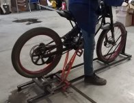
OK back on topic. I have 6 motor run caps on order. I found you can put a cap between phases on an induction motor and it will produce ac voltage. So my plan is to play with the cap values to see what I can pull out then rectify it and put the power back into the pack. Hopefully I will get some power back into the pack this way. My plan is to hook one of my induction motors to the end of my roller for a added load. It should work well enough to add a steady load and I am hoping to run the electric motors I'm testing coupled strait to the other end of the induction motor to do motor only testing with the option to use the big roller for an inertia load strait on the motor as well.

Now my question is how do I vary the load or regen from the induction motor? Can I vary the capacitance or can I use a light dimmer in series with the caps??
 
I am trying to download Simple dyno software but given link is not working. Can you provide me Simple dyno software

kadir
 
https://sites.google.com/site/simpledyno/file-cabinet got to get to work teaching a class latter. :)
 
We tried several times but unfortunately we could not open this web page https://sites.google.com/site/simpledyno/file-cabinet

any other web page ? or can you send us fies as ZIP format ?
 
I am sorry , I just found the solution. It was because of my DNS setting. Now I have to software.

Could you please tell me where can I find "SD6_3 Sketch.ino" file ?
 
Did a coast down run for more accurate testing.

And got it al working about right. Measuring a 75-5 zero motor in my DIY bike at 45hp with a size 4.
[youtube]dMPYrFRdNNU[/youtube]

[youtube]0hNctGBDMTs[/youtube]
 
Arlo, did you played with the sevcon parameters with the current control PI and gain etc?.. I just installed the 75-7 motor on my 2012 S and it work well but i'm having some overdamping at above 110kmh... Ryan gave me some advices to look at. itMS not easy to program as the infineon.. lol.. just as Luke said already!

But i want to understand all these parameters... not an easy task !

I'm playing with the dcf files and modifying some and compare some with winmerge to isolate some value that vary from oen DCF to another...

I have to understand where are these parameters that affect the field weakning...

Doc
 
Doctorbass said:
Arlo, did you played with the sevcon parameters with the current control PI and gain etc?.. I just installed the 75-7 motor on my 2012 S and it work well but i'm having some overdamping at above 110kmh... Ryan gave me some advices to look at. itMS not easy to program as the infineon.. lol.. just as Luke said already!

But i want to understand all these parameters... not an easy task !

I'm playing with the dcf files and modifying some and compare some with winmerge to isolate some value that vary from oen DCF to another...

I have to understand where are these parameters that affect the field weakning...

Doc
No. I want to experiment with field weakening but I don't fully understand it yet.
I have found a lot of settings that stop the motor and shut the contactor off lol. It is easy to mess up a sevcon.
 
Hello Arlo,
We got a sympledyno setup rolling to test pour LMX (10kw battery side)
We have a arduino with hall sensor and 12 magnet encoder wheel, works well. The issue is that when we read the battery voltage and current with shunt (battery gnd to arduino gnd, with voltage divider) the interrupt gets triggered all over the place for rpm measurements.
How did you do voltage and current measurements on your setup? We tried software denounce with no luck.

We use a asynchronous motor rotor as the roller and we added a truck disk brake for inertia, we can add a truck drumm too if we need more but it's hard to balance at 3k rpm.

Thanks! Adam
 

Attachments

  • IMG_20160326_105709.jpg
    IMG_20160326_105709.jpg
    35.1 KB · Views: 2,644
  • Screenshot_2016-03-26-12-50-52_com.miui.video_1458993133978.jpg
    Screenshot_2016-03-26-12-50-52_com.miui.video_1458993133978.jpg
    74.5 KB · Views: 1,964
bzhwindtalker said:
Hello Arlo,
We got a sympledyno setup rolling to test pour LMX (10kw battery side)
We have a arduino with hall sensor and 12 magnet encoder wheel, works well. The issue is that when we read the battery voltage and current with shunt (battery gnd to arduino gnd, with voltage divider) the interrupt gets triggered all over the place for rpm measurements.
How did you do voltage and current measurements on your setup? We tried software denounce with no luck.

We use a asynchronous motor rotor as the roller and we added a truck disk brake for inertia, we can add a truck drumm too if we need more but it's hard to balance at 3k rpm.

Thanks! Adam
I used a Hall type current sensor. http://www.digikey.ca/product-detail/en/honeywell-sensing-and-productivity-solutions/CSLA2EN/480-4827-ND/3072999
CSLA2en is a 950 amp AC/DC current sensor digikey number 480-4827-ND
I have some 400 amp sensors that are very similar and they work well. You want to find one that will work for everything. What I do when I dyno lower power things is I run two (or more) loops though the sensor and that makes it have a better resolution. You can set it all up to read correctly with the simple dyno software.
Using that current sensor is better then a shunt. Then you don't get all the noise introduced into both the current signal and the battery voltage.

I use a optic sensor for the trigger and I had to go to 1 signal per rev to make it clean.
I use one of 2 voltage dividers that produce 5v at 100v or 5v at 200v (made 2 options for better resolution.)
I put a small cap on all signals to filter the noise.
I use a lap top power supply for power for the Arduino and a supply for the current sensor which uses a regulated 10v in then it goes to a 2:1 divider out to the Arduino for a 2.5v center point and 1.38v at -950 and 3.164 at +950 amps
Hope this helps.
 
PS did you see this? I have a dual controller bike set up :) So far 87hp at the wheel is my record.

[youtube]3eL0EMFPnVw[/youtube]


This one explains it a bit better.

[youtube]-Eghh0mHdx8[/youtube]
 
Thanks for the tips, for the current sensor indeed better change it for hall effect, but first I really have to make battery voltage and the RPM work well together.
 
bzhwindtalker said:
Thanks for the tips, for the current sensor indeed better change it for hall effect, but first I really have to make battery voltage and the RPM work well together.
A voltage divider is really easy to use that takes the battery voltage and divides it down to 0-5v just don't put more then 5v into the Arduino.
 
Yes we have one, its calibrated and reads quite precisely after calibration, but it's causing unwanted triggering of interrupts when the motor spins, how did you isolate from noise exactly?
 
Martin A said:
Is the dual controller bike motor 6 phase and being split into 2 x 3 phase like John in CR's Hubmonster?
The Zero motors are wound as 2 separate 3phase motors in side. Then under the cover they are connected in parallel.
 
Got our dyno runing by separating the RPM sensing from the arduino and using an external audio card for that.
Now figure how to proprely calibrate the inertia to get accurate results! do you have inputs on that? Also, voltage and current readings are quite noisy (seems like too low sampling speed) did you have issues with that?
file.php

Adam
RUN1 inertial.jpg
 
bzhwindtalker said:
Got our dyno runing by separating the RPM sensing from the arduino and using an external audio card for that.
Now figure how to proprely calibrate the inertia to get accurate results! do you have inputs on that? Also, voltage and current readings are quite noisy (seems like too low sampling speed) did you have issues with that?
file.php

Adam
Calibrate inertia? Or do you mean a run down test to find the roller drag?
I use small caps on the signals to clean them up ~10uf if ok for the 0-5v signals for the current and voltage
 
Back
Top