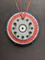
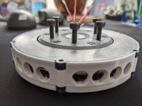
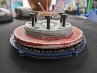
DIY Toroidal Axial Flux PM

Well today was productive.

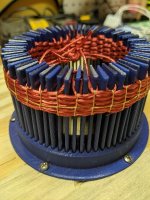
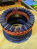
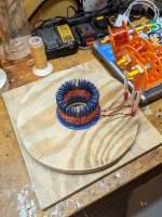
First, I had a lazy Susan bearing from a while back that I actually thought I could make a motor with. I used it to make a turn table with the winding jig in the center. This has been awesome. I drilled some holes in it to hold the pens while I wind it, but I think I might make better holders as they don't stay in nicely all the time, and they are in the way when they are vertical that close to the center. Ill try to angle them out.

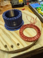
I still have quite a bit of wire on the weird pen tools that I made a while back, and that got me a 6 turn stator. Just need to prep the mold again. I might just try with the epoxy I have now. I have some stuff that's not table top epoxy but I don't know if its any better from a glass transition or thermal conductivity standpoint.

After thinking a bit more about the epoxy subject today. I decided if I really want to make this work as a motor, it would have to be cured in some sort of oven. So this has me at a bit of a dilemma. Can I cure it at temp while under pressure? how would I do that. The 3d printed mold likely will not stand up to the curing temps, it will either melt and/or fuse together. So how do I even press it while its curing at temp.

One thought I had was to get an epoxy that I can cure for a while at a lower temp, then I could move it to an oven for the next steps, and hopefully It wouldn't need to be in the press for that stage.

Also, what would be a reasonable oven to cure it in, a little convection oven?

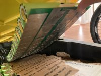
anyway, check these pics out from today.
resized-image-Promo - 2022-01-17T170537.020.jpeg
resized-image-Promo - 2022-01-17T170557.639.jpeg
resized-image-Promo - 2022-01-17T170615.155.jpeg
resized-image-Promo - 2022-01-17T170634.655.jpeg
resized-image-Promo - 2022-01-17T170653.185.jpeg
resized-image-Promo - 2022-01-17T170717.748.jpeg
 
HalbachHero said:
Well today was productive.

First, I had a lazy Susan bearing from a while back that I actually thought I could make a motor with. I used it to make a turn table with the winding jig in the center. This has been awesome. I drilled some holes in it to hold the pens while I wind it, but I think I might make better holders as they don't stay in nicely all the time, and they are in the way when they are vertical that close to the center. Ill try to angle them out.

I still have quite a bit of wire on the weird pen tools that I made a while back, and that got me a 6 turn stator. Just need to prep the mold again. I might just try with the epoxy I have now. I have some stuff that's not table top epoxy but I don't know if its any better from a glass transition or thermal conductivity standpoint.

After thinking a bit more about the epoxy subject today. I decided if I really want to make this work as a motor, it would have to be cured in some sort of oven. So this has me at a bit of a dilemma. Can I cure it at temp while under pressure? how would I do that. The 3d printed mold likely will not stand up to the curing temps, it will either melt and/or fuse together. So how do I even press it while its curing at temp.

One thought I had was to get an epoxy that I can cure for a while at a lower temp, then I could move it to an oven for the next steps, and hopefully It wouldn't need to be in the press for that stage.

Also, what would be a reasonable oven to cure it in, a little convection oven?

anyway, check these pics out from today.
resized-image-Promo - 2022-01-17T170537.020.jpeg
resized-image-Promo - 2022-01-17T170557.639.jpeg
resized-image-Promo - 2022-01-17T170615.155.jpeg
resized-image-Promo - 2022-01-17T170634.655.jpeg
resized-image-Promo - 2022-01-17T170653.185.jpeg
resized-image-Promo - 2022-01-17T170717.748.jpeg

Outstanding results now...
 
HalbachHero said:
...it would have to be cured in some sort of oven. So this has me at a bit of a dilemma. Can I cure it at temp while under pressure? how would I do that. The 3d printed mold likely will not stand up to the curing temps, it will either melt and/or fuse together. So how do I even press it while its curing at temp.

One thought I had was to get an epoxy that I can cure for a while at a lower temp, then I could move it to an oven for the next steps, and hopefully It wouldn't need to be in the press for that stage.

It depends on the resin you use. Baking it after / outside the pressure pot might allow the air bubbles to expand (soft resin) and distort. Or do a low temp pre-cure, pop it out of the mold and back in the pot and then do a full temp bake.

You can likely use a higher temp plastic for the press. I just bought some 360°F rated SLA resin to try for fiberglass molds. Requires printing at 85°F+ though.

Also, what would be a reasonable oven to cure it in, a little convection oven?

You have some choices. You can put the pressure pot in a small oven but this sounds very sketchy to me.
You can buy silicone heating elements with temperature controllers. Stick it to the bottom or around the outside of the pressure pot and it will warm the pot. Make sure it works as expected before filling / pressurizing. Some of these silicone pad heaters can melt themselves and some are thermally limited.
Think of the wattage you would need as an incandescent bulb. Or, 100 watts of heat would probably do it.
You'll have to be careful to not heat past the seal or lid (if plastic) temp of the pressure pot. I'd guess your printed parts are more heat sensitive though.
Also make sure you don't go lighting a table on fire from the heater. Adding heat adds risks.

These are looking good!

Is it worth using a pcb as the base / bolt holes or a 3D printed stator with the winding jig spots built in? If you wanted to get some iron in there you might be able to replace the plastic "blades" with laminations or do a second mold / casting step to do some soft powdered iron cores.
 
TorontoBuilder said:
Outstanding results now...
Thanks! It sure has come a long way

Jrbe said:
It depends on the resin you use. Baking it after / outside the pressure pot might allow the air bubbles to expand (soft resin) and distort. Or do a low temp pre-cure, pop it out of the mold and back in the pot and then do a full temp bake
Do you think that I could use an epoxy with a long pot life, and potentially degas it first? Then do the whole low temp pre-cure, to a heated cure.
In this case do you think I would need pressure at all? could it go right in an oven?

Jrbe said:
You have some choices. You can put the pressure pot in a small oven but this sounds very sketchy to me.
yes, I agree. I don't think my wife would approve. I might need to get power to my shed for something like that haha.

Jrbe said:
You can buy silicone heating elements with temperature controllers
I like this idea. I still feel weird about the heat and pressure, but the pot is all metal (harbor freight). I can test in small increments of heat and pressure, but I would love to find a way to do this without the pressure pot for the heated cure stage

Jrbe said:
Is it worth using a pcb as the base / bolt holes or a 3D printed stator with the winding jig spots built in? If you wanted to get some iron in there you might be able to replace the plastic "blades" with laminations or do a second mold / casting step to do some soft powdered iron cores.
So this subject is where my mind had been lately...
I don't want to use PCB unless I can get it created cheaply. I feel It would need 3 dimensional aspects, so that it couldnt be laser cut. But I might be underestimating the stiffness of a 1.5mm chunk of PCB, and I might be able to make it really thin and a 2D shape would work.
Also If you look back to my stators that were 3D printed, they had a benefit, of a mounting point in the center of the stator with the windings on the outside. I was limited to how think I could print this, but I was able to fit 6 turns on it, which might be ideal anyway. So I have considered either going back to that, (would have to be 3 printed or some how cast from a mold, but eve that seems tough) OR I can try to make a disk with the coils on either face. Maybe two smaller stators wired together.
If I did this I could make slots the shape of the plastic "blades" on the winding jig. I could make a bunch of "blades" out of powered iron and epoxy, insert them into the slots, put the two stators on and re-press/pot all of that together.

BUT...
- I am not sure how the two stators would work together.
- Wouldn't it be easier to keep one stator, avoid the PCB, and use a iron powder epoxy for the whole thing? (keeping some center piece to keep the epoxy only around the coils)

Curious of others thoughts too
 
You could likely degas the resin after mixing, slightly overfill the mold, then degas the resin while it's in the mold again. Having tall risers (sprue too) in the mold helps it not "boil over" everywhere. Problem with the risers though is the extra resin will leave extra peaks to have to trim.
You should be able to find a large paper cup or a plastic mixing container to put in the vacuum pot to keep it clean if you haven't already.
You could also centrifuge cure it too. Basically spin it while it cures. The bubbles will go to the middle. Adding heat could be challenging.

How hot are you looking to go? The pressure will rise as it heats but it should have a safety valve built in. Is the pressure pot seal captured? If it is, when it starts melting it will likely leak instead of blow out. But yeah, it's nice to be able to experiment outdoors (and safely) with new things. I'd expect there is a temp range that the pot is rated for though.

Any question about resin is hard to answer generically. There are so many different resins with different cure requirements. Some resins won't cure at room temp, they have to be baked. Some can be mixed then frozen until you're ready to use it.

As for adding iron I'm not sure you want iron in all of the stator - I'd expect the coils ahead and behind would fight the magnetic field of the coil you're thinking of. You could likely wrap the copper around some cores then pot it. You could make some "straws" to fit over the cores so it's like your winding assist "blades" currently. Think your blades just hollow on the bottoms to slip over the cores.
Alternatively you could do a 2 step potting process with 2 different molds or inserts. 1 to leave "windows" for iron and a second step with iron filled resin. Something like this, 1vdn-12e502af0c5a737fe0cbfc96536ae048.jpg
Then part 2 fills the windows with some core material.

You could build a stator many different ways. Wound as you are now, Individual coils, coils in a phase grouped, etc.

PCB's can be bought very inexpensively and in different thicknesses and materials. You don't have to use the copper layer for anything https://cart.jlcpcb.com/quote
or www.pcbway.com (pricier but more options.)
You'll probably pay more for shipping than for the PCB's. It might not make sense for your motor, but they can be an easy way to get milled fiberglass or aluminum sheets to your shape to build off of. You could add in circuitry for hall sensors, temp sensor, etc. if you wanted to.
What might help is to think about a foam core composite panel. Foam is pretty useless strength-wise by itself but use it as a sandwich core with composites on each outer side and it makes a very strong part. Your coils would be inside. As long as the 2 PCBs get glued together as the outsides of the sandwich it will be strong. You would have to scuff up the PCB's before potting them. But this will likely trap heat inside.
You could also do 1 pcb in the center and build the stator around it as well.

Lots of different options. Usually it makes sense to use what you're comfortable with then try some other ideas once you have a base to compare to.

I'm toying with building a PCB motor using aluminum PCB's for the rotor and maybe fiberglass with the copper traces as the windings in the stator (maybe multiples stacked.) https://endless-sphere.com/forums/viewtopic.php?f=30&t=113695 I'm not far enough along to show you my thoughts though. Keeping the traces cool will likely be a big challenge.
 
Jrbe said:
You could likely degas the resin after mixing, slightly overfill the mold, then degas the resin while it's in the mold again. Having tall risers (sprue too) in the mold helps it not "boil over" everywhere. Problem with the risers though is the extra resin will leave extra peaks to have to trim.

I'll try this if I can, just need to get something with a long handling time. The epoxy the comes up the risers is not an issue it seems, they either pull out of the riser holes, or snap off. and they are such a small diameter, cleaning them up is easy.

Jrbe said:
How hot are you looking to go?
Im using N52 magnets in my motor, future versions might use a lower grade if these demagnetize, but N52 will demagnetize at ~80C so I would want to at least push the glass transition temp beyond that. I also am not sure is using something thermally conductive is a good idea or not. If I trap the heat, I could save the magnets, but I imagine that would create a bit of a negative feedback loop. I think ideally I would let the heat escape to the outside and then wick it away with something, air or maybe liquid?

Jrbe said:
Is the pressure pot seal captured?
Not sure what you mean. its a really cheap, crappy seal. It appears to be a hard silicone or maybe plastic, but it sucks. It leaks at like 25PSI (the pot is rated for 60PSI) not matter how tight I get it. I think I can fix it easy enough, maybe rip it out and make my own silicone one. But yeah the pot has a bleeder valve on it too.

Jrbe said:
As for adding iron I'm not sure you want iron in all of the stator - I'd expect the coils ahead and behind would fight the magnetic field of the coil you're thinking of
I wansn't sure if this was the case or not. I think I will try the way I was thinking before. I am going to make Iron powder "blades", and insert them between the legs of the stator while its in the press, and see where that gets me.

I keep going back and forth with the PCB motor idea, while it is convenient, I think that the traces will never handle the current that you would want. I like the idea of having the freedom to use more or less strands easily, or higher or lower gauge wire. I think it makes it a platform for motors of various purpose.

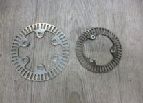
Also, where did you get that photo, because that looks very similar to what I have going on there.


I was messing with the jig, and tried to separate it while it was still bolted, like a big dumb idiot, and broke it. (don't drink and build). I tried to glue it, but it did not align correctly, so I'm just printing another one. Also the risers totally got clogged. I need to either redesign things a bit more or find a better way to knock the plugs of epoxy out.
Once the new top is printed I'll press this stator with no iron, fiberglass tow, and the fiberglass sheets.

Oh, also, now that the epoxy totally cured on the last stator. I yanked on it a bit, its really stuck on the center hub. very happy with how that turned out. I would still like to do a comparison, but theres so much to do.

Next steps might be tinkering with making iron cores, but I have a pretty good idea how I want to make them. I am just not sure what I should make them out of. I have some iron powder. but is there maybe something better?
 
you could get magnets capable of much higher temp than 80c. https://www.kjmagnetics.com/specs.asp

pcbs do have thin traces but with the possibility of making them very wide you can get good conductivity. this is a pcb for a battery and equivalent to 10awg wire. If a design could be made using a pcb not only for orienting the wires but being the coils that could maybe make it much easier..if possible.


getting the resin with few bubbles shouldnt be hard with just a a vacuum pump/chamber. Even without I bet you could get results mixing and pouring slowly and using a resin with a long cure time that's heated to make it even thinner.
 

Attachments

  • EC0C68BF-199E-4697-B364-1BDDD9CEC273.jpeg
    EC0C68BF-199E-4697-B364-1BDDD9CEC273.jpeg
    3.6 MB · Views: 1,372
Hummina Shadeeba said:
you could get magnets capable of much higher temp than 80c. https://www.kjmagnetics.com/specs.asp

pcbs do have thin traces but with the possibility of making them very wide you can get good conductivity. this is a pcb for a battery and equivalent to 10awg wire. If a design could be made using a pcb not only for orienting the wires but being the coils that could maybe make it much easier..if possible.


getting the resin with few bubbles shouldnt be hard with just a a vacuum pump/chamber. Even without I bet you could get results mixing and pouring slowly and using a resin with a long cure time that's heated to make it even thinner.

multilayer pcbs have been used in coreless motors they just lack the power of a cored motor.
 
HalbachHero said:
Jrbe said:
You could likely degas the resin after mixing, slightly overfill the mold, then degas the resin while it's in the mold again. Having tall risers (sprue too) in the mold helps it not "boil over" everywhere. Problem with the risers though is the extra resin will leave extra peaks to have to trim.

I'll try this if I can, just need to get something with a long handling time. The epoxy the comes up the risers is not an issue it seems, they either pull out of the riser holes, or snap off. and they are such a small diameter, cleaning them up is easy.
Thats great to hear the risers are not an issue for the stator.

Might be worth trying the silicone insert tube method for the risers with your broken mold before you print a new one. You could use a funnel or a syringe to fill through one of the tubes too if you wanted.

Jrbe said:
How hot are you looking to go?

HalbachHero said:
Im using N52 magnets in my motor, future versions might use a lower grade if these demagnetize, but N52 will demagnetize at ~80C so I would want to at least push the glass transition temp beyond that. I also am not sure is using something thermally conductive is a good idea or not. If I trap the heat, I could save the magnets, but I imagine that would create a bit of a negative feedback loop. I think ideally I would let the heat escape to the outside and then wick it away with something, air or maybe liquid?
Resins have a cure profile spec. The glass transition temp is different than the cure temp. Usually they are all higher together but are not necessarily related / linked. I don't think it will be hard to find a potting epoxy with a 80°C + temp rating.
Not potting epoxy and pretty old but decent list, https://www.rocketryforum.com/threads/list-of-epoxy-systems.62308/

HalbachHero said:
Not sure what you mean. its a really cheap, crappy seal. It appears to be a hard silicone or maybe plastic, but it sucks. It leaks at like 25PSI (the pot is rated for 60PSI) not matter how tight I get it. I think I can fix it easy enough, maybe rip it out and make my own silicone one. But yeah the pot has a bleeder valve on it too.
[/quote]
Captured means there is a wall / ledge / groove or something to hold the seal in place. Sounds like they didn't do so well in the design of the seal. Did you get one that was sitting around for a while and got dry? Maybe warped? Heat will usually help soften the seal but sounds like it will probably be a struggle.
Worth returning it? Harbor Freight stuff seems to be ok or bad.

Jrbe said:
As for adding iron I'm not sure you want iron in all of the stator - I'd expect the coils ahead and behind would fight the magnetic field of the coil you're thinking of


HalbachHero said:
I wansn't sure if this was the case or not. I think I will try the way I was thinking before. I am going to make Iron powder "blades", and insert them between the legs of the stator while its in the press, and see where that gets me.
It may or may not be the case. FEMM would likely be a good place to start. I am by no means an expert on magnetics.

HalbachHero said:
I keep going back and forth with the PCB motor idea, while it is convenient, I think that the traces will never handle the current that you would want. I like the idea of having the freedom to use more or less strands easily, or higher or lower gauge wire. I think it makes it a platform for motors of various purpose.
I'm ok burning some up learning. There are 3 winding methods to try and a few ways to get the heat out to try. I'm trying to stay at 2oz copper thickness to keep the PCB's cheap. Copper conducts heat well. My plan is to use some vias and some dead end traces to "heat pipe" the heat to the outer edges and to some water cooling tubes. Thinking about how to add iron cores too. I dont want to muck up your thread so I'll stop there. Was just an idea to be able to buy cheap fiberglass stator cores that you could wind similar to how you are now or still using copper traces as the coils but a PCB as a base - if it made sense for you.

HalbachHero said:
Also, where did you get that photo, because that looks very similar to what I have going on there.
Those are KTM Duke (motorcycle) ABS toner rings.

HalbachHero said:
Next steps might be tinkering with making iron cores, but I have a pretty good idea how I want to make them. I am just not sure what I should make them out of. I have some iron powder. but is there maybe something better?

There are iron powders that are insulated (SMC - soft magnetic composite). Idea being they do not conduct electrically but do conduct magnetically. They are usually pressed and sintered but could be glued together (less effective.) There are different mixes with different minerals, different sizes, etc. At lower frequencies they are comparable efficiency wise to laminated cores.
I was watching this last night, https://www.youtube.com/watch?v=YQNW4ZTsg2w These are the struggles I've read here as well trying to make cores. Might be worth trying a centrifuge method when making them (iron will go to the outside, extra resin will go to the inside. Still wont get to the recommended pressed densities that way though. Maybe borrow SpinLaunch's setup?

Also lots of different studies / info you can dig through (i've been looking too):
https://www.researchgate.net/search?q=insulated%20iron%20powder
https://www.researchgate.net/search/publication?q=smc+motor+core
https://magneticsmag.com/insulated-iron-powders-smc-current-state-and-future-possibilities/
https://sumitomoelectric.com/sites/default/files/2020-12/download_documents/82-02.pdf
https://www.nist.gov/system/files/documents/pml/high_megawatt/Ohodnicki-DOE_SoftMagneticMaterialsForElectricMachines_NIST_Ohodnicki_9_10_2015.pdf
https://drive.google.com/drive/u/0/folders/1oWwLWvIUTucV_SlYJL8cxMjAyaBCQqze
 
1 more on how Hoganas smc cores are made,
https://www.jmag-international.com/motordesign-material/hoganas_001/
 
you can forget trying to purchase hoganas' powders but there are similar ones available in smaller quantities via alibaba.

The usual caveats apply... you need to search thru BS and lies to find reputable vendor who will sell low quantities. I went thru this and many tried to sell me powders that were not conductively insulated. The powders need to have oxide coating IIRC aluminum oxide or similar.

I'm going to try epoxy and smc powder cores for my motor for my flying Merkel.
 
TorontoBuilder said:
you can forget trying to purchase hoganas' powders but there are similar ones available in smaller quantities via alibaba.

The usual caveats apply... you need to search thru BS and lies to find reputable vendor who will sell low quantities. I went thru this and many tried to sell me powders that were not conductively insulated. The powders need to have oxide coating IIRC aluminum oxide or similar.

I'm going to try epoxy and smc powder cores for my motor for my flying Merkel.

It would be great to post the info here on ES if anyone has solid leads on smc powder or useful smc cores.
 
Jrbe said:
You could use a funnel or a syringe to fill through one of the tubes too if you wanted.
My concern with the syringe here or funnel would be that it would not completely fill. I don't have too much trouble just pouring it. but I understand that it could help avoid air bubbles in the resin. Maybe another experiment is in order.

Jrbe said:
Resins have a cure profile spec. The glass transition temp is different than the cure temp. Usually they are all higher together but are not necessarily related / linked. I don't think it will be hard to find a potting epoxy with a 80°C + temp rating.
Thanks for the link around this I will sift through and see what I fits the bill.

Jrbe said:
Captured means there is a wall / ledge / groove or something to hold the seal in place. Sounds like they didn't do so well in the design of the seal. Did you get one that was sitting around for a while and got dry? Maybe warped? Heat will usually help soften the seal but sounds like it will probably be a struggle.
Worth returning it? Harbor Freight stuff seems to be ok or bad.
Gotcha. Yeah it is captured. but the seal is garbage. I will spend a little time trying to fix it, if that doesnt work ill get a new better one. The one I got from harbor freight was a paint tank. I just converted it with a few fittings, which is the same reason why I can't return it now.

Jrbe said:
It may or may not be the case. FEMM would likely be a good place to start. I am by no means an expert on magnetics.
I have been wanting to tinker with FEMM again a bit.... maybe a good excuse. If anyone wants to help me with a bunch of axial flux motor formulas. I might be able to make my web app a bit more useful


Jrbe said:
Copper conducts heat well. My plan is to use some vias and some dead end traces to "heat pipe" the heat to the outer edges and to some water cooling tubes
Nice I have seen the copper dead ends used before. I will definitely continue to follow your thread. I would love to see someone pursue PCB stators, I might try them myself, but its just a whole new realm of learning that I'm not 100% ready for yet.


Jrbe said:
Maybe borrow SpinLaunch's setup?
To the moon! haha yeah that would be something. but I hear what youre saying. I wonder how realistic a centrifuge is.. I would think you would need some serious RPM to compact it though.


TorontoBuilder said:
I'm going to try epoxy and smc powder cores for my motor for my flying Merkel
Were you able to find some SMC powder with coatings?


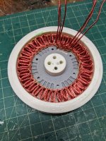
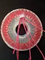
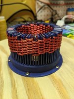
And for progress... I pressed and potted the 6 turn copper. This sort of worked. I tried to fit all 6 wires through the hole I had created, and I was able to, but it was very tight, and the extra epoxy pushed up through and caused everything to get stuck when pulling things out. I think I will try to use some silicone tube for this next time, that way even with epoxy it should slide out after. Also this could be used to prevent any heat from the wirer touching a 3d printed part directly. Because of things getting stuck, it looks like I broke some strands in the process of removing things which I kind of expected given how hard it was to remove, but all in all. I really like how it turned out. I only let it cure about 36 hours. and this stuff need 72. so I will wait another day to test it, but its looking good. Just need to clean the clay out of the mounting holes, and solder the connections. Then I'll give it a test.

This version did not have the fiberglass tow in it. I know I said I would, but for a few reasons I did not. I will likely use it on the next one.

Oh also, this was using the 4.5mm press top that I tried with the last nylon stator, and strangely this one is coming out to about 5.2mm. I'm not sure if maybe I sanded too much off of the top part before pressing, or if the copper didn't want to compress that much ( I don't think this was the problem). or most likely, that the press separated a bit curing the process, and I did not really have it locked down while curing. The wood that I had around it was used a few times, and I don't think the screws were grabbing it tightly

I am going to redesign the mold a bit to hopefully resolve some of the issues that I have had with these.

But check this out!
resized-image-Promo - 2022-01-23T170524.015.jpeg
resized-image-Promo - 2022-01-23T170544.793.jpeg
 
Hummina Shadeeba said:
you could get magnets capable of much higher temp than 80c. https://www.kjmagnetics.com/specs.asp

pcbs do have thin traces but with the possibility of making them very wide you can get good conductivity. this is a pcb for a battery and equivalent to 10awg wire. If a design could be made using a pcb not only for orienting the wires but being the coils that could maybe make it much easier..if possible.


getting the resin with few bubbles shouldnt be hard with just a a vacuum pump/chamber. Even without I bet you could get results mixing and pouring slowly and using a resin with a long cure time that's heated to make it even thinner.

Have to be careful with PCB traces in a motor. They are in the right orientation to suffer massive Eddie currents on wide traces. You would have to split the wide trace into loads of smaller traces.

I was a big proponent of using a PCB trace until this hit me the other day like bleurgh.


Another beautiful stator Halbach Hero. That plus the lasered metal, I expect goodness.
 
mxlemming said:
You would have to split the wide trace into loads of smaller traces.
And the wider the traces, the wider the spacing between, which results in wasted space. You might be able to stagger them between layers, but there would always be a gap. Its hard to say if its still more densely packed than something hand wound. Would love to see a comparison with the same topology.

mxlemming said:
Another beautiful stator Halbach Hero. That plus the lasered metal, I expect goodness.
Thanks! me too. I wish I didn't ruin some of the strands, but that's the benefit of this new design, I can just make another one and swap it out.


I soldered the ends, attempting to salvage all the strands I could for some of the wires. I am printing a new hub for stator, since the one I had did not line up with where the phase wires came out. Then I will need to add the heat set inserts and make a new mount for this one. I might be able to get some hand spun Kv measurements before thee mount is done though. it doesn't mean much but just holding the stator by hand and spinning both rotors around it, I can easily get 300mv on a single phase. very excited to see what it actually is.
 
Hummina Shadeeba said:
I wonder how this place does it with pcbs and they make big claims
https://pcbstator.com/news/modernised-motors-high-performance-solutions

This looks like high budget stuff where PCBs stacked many many layers high and a very high copper to fibreglass ratio or maybe kapton is realistic.

With stacked kapton PCBs you could get excellent power density and run at 200 degrees easily.

Looking at the pics their traces are narrow.

Then there's probably a ton of hype and half truths
 
Looking good halbachhero.

The inner and outer edge are low in resin. It's hard to get the edges to wet out. Might be worth wetting the fiberglass rings ahead of time.

You could also make some pegs to keep the bolt holes from filling. If you get the taper right they could hold, seal, and be reusable.

Hummina Shadeeba said:
I wonder how this place does it with pcbs and they make big claims
https://pcbstator.com/news/modernised-motors-high-performance-solutions
Those are the "heat pipes" I mentioned. They have VC claims and mention starting in HVAC - low startup torque?

I think cores could be added to a pcb stator easily. The tough part I see is getting the heat out. Maybe some non-electrically conductive, thermally conductive paste /epoxy to bring the heat out to some water tubes?
Slots outside the coil and magnet area to weave heat tubes through the PCB's?
Easy to add a temp sensor mid stack as well as halls.
My thought was to use thin traces on many thin PCB's like a "flat" litz coil. For a quantity of 100 .4mm thick 1oz pcbs on JLC they're about $130 but are ENIG (not sure if that would be bad or good.)

The best litz pcb trace reference I've found,
https://www.mdpi.com/2079-9292/9/8/1324/htm

This is the best lead I've found for cores / core material,
http://www.changsung.com/cores?lang=en
And
http://www.mhw-intl.com/assets/CSC/CSC_Catalog.pdf

I haven't tried to contact them yet.
 
I had previously found a alibaba vendor who claimed to have smc powder but I can't find them at the moment.

I have leads on UK and US vendors but I wanted to call them to assure that they can supply small batches before I post links to them and po9tentially inundate them with requests they wont serve
 
Since there are spaces between the coils, it would not be hard to put little slices of iron lamination between them. Much higher saturation flux than powder mixed in epoxy.
 
I wonder if a layer of kapton tape over the magnets would be useful.

Jrbe said:
The inner and outer edge are low in resin. It's hard to get the edges to wet out. Might be worth wetting the fiberglass rings ahead of time.
If you are referring to the white parts of the fiberglass, that is actually paint. I made a stencil and spray painted the inner and outer diameter. the spray paint is a white enamel paint. It helps with keeping the fibers orderly when cutting out the disk.
Everything seems pretty wetted out, but there are some bubbles in the due to the pressure pot not holding pressure over time. (in the morning it was totally depressurized.)

TorontoBuilder said:
I have leads on UK and US vendors but I wanted to call them to assure that they can supply small batches before I post links to them and po9tentially inundate them with requests they wont serve
That's good news, would love to hear what you find out.

fechter said:
Since there are spaces between the coils, it would not be hard to put little slices of iron lamination between them. Much higher saturation flux than powder mixed in epoxy.
Unfortunately I do not have the means of cutting up laminations in small chunks accurately like that. If any one wants to do that and ship them to me, I will try it, but yeah I would have to cut everything by hand and I don't think I would get what I'm hoping for.


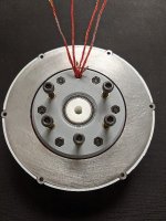
I got it all mostly hooked up. There are some tolerance issues still. I have made some tweaks to the parts, and will put this modular set up to use. the air gaps are multiple millimeters right now since I changed from a 6.5mm stator to a 4.5 (which actually came out 5-5.2mm).

But ain't she pretty?
resized-image-Promo - 2022-01-25T094759.903.jpeg
resized-image-Promo - 2022-01-25T094910.955.jpeg
resized-image-Promo - 2022-01-25T094847.477.jpeg
resized-image-Promo - 2022-01-25T094929.545.jpeg
 
Hummina Shadeeba said:
If ur testing till destruction with high speed or high current please get it on vid. Please tell the test and I’m hoping we can post bets
I like the way you think....
Max RPM and max current? anything else?

I get the feeling it will melt pretty easily. I would love to see if I can hit 10k RPM
 
without a dyno or load you can add to test torque i guess just go for max speed! the motor not having any iron makes it seem especially a high speed motor and where its power will be and then youd gear it down.

maybe before going full speed balance the rotor. Ive heard you could try a laser pointer fixed to the stator thats pointing at a wall and add or subtract material with the goal of getting the laser point stable as you remove vibrations. sounds fun. never done it.

eventually i guess a magnet will fly off like a missile though and surely dangerous, surely you know. peak power maybe could be way higher if you can fix the magnets better and then ..double the speed. I think you should add long kevlar strands wrapped around the outside of the magnets!
 
A word about sourcing powders for use in the manufacture of soft magnetic composites.

Much of the issue with trying to source powder in low volumes is the fact that there is not a "single" powder, but rather there are various classes of powders primarily developed for compaction in dies and then annealing to increase the density and strength of the part.

Most manufacturers are not forthcoming in marketing materials about the composition of their powders so trying to source from other than Hoeganaes is very difficult. Sourcing from Hoeganaes is next to impossible. In order to source from other vendors you need to know a bit about what you are looking for.

Early insulated powders used polymers or phosphate coatings in their manufacturing process. These coatings can not be annealed at sufficiently high a temperature to provide high strength because the insulative coating would break down at progressively higher temperatures and the resistivity would reach zero around 600 deg C.

Lower resistivity of many powders for SMC meant that they were only suitable for lower frequencies because core losses become too high over 400 HZ.

New water atomized processes have been developed to create Iron powders with oxide coatings that can withstand high temperature sintering processes and that have outstanding electrical resistivity making them suitable for use at very high frequencies.

As previously mentioned, you can find the trade names for a number of potentially suitable powder products from Hoeganaes but you cannot order any unless you are a large manufacturer. So the trade names dont help much.

If you search SMC on wholesale and retail sites like alibaba or made in china you will be inundated with soft sheet magnets and other garbage that is unrelated to what you want. Similar useless results come from searches on electrically resistive iron powders, smc iron powders, powder metallurgy will return 100s of powders that lack insulative coating.

So what you really need are the right search terms for specific powder metallurgy make up.

Then there is the issue of intended use. If you plan to cast a powder in epoxy resin you don't need the latest most expensive powder developed for press compaction and high temperature sintering. I believe that merely mixing plain iron powder in electrically resistant high temperature epoxy may work in many DIY applications and provide greater efficiency than coreless motors. Those results can be potentially bolstered with a better coated powder if we can obtain some.

As I said I have contacted a few sources that supply low volumes typically for experimental uses. One company in the USA will sell to individuals without a corporate entity which is great. I expect a quote within the next few days, and I shall let you know. It may require a larger volume purchase than a couple of kilograms. In such a case I'd see if we could perhaps do a group buy.
 
Back
Top