Arlo's power stage Leaf controller runs and drives page 103

nieles said:
arlo, could you post a dyno plot with x-axis, torque (at the wheel) and y-axis wheel rpm.

awesome vids by the way!

No... Sorry Damon at Simple dyno wrote the program to read roller torque. SO you can add 12% ( x 112 ) to the torque numbers.
This run is before I paralleld the ends of the lipo. I was just pulling power through the methods ballance boards from the out side two strings of lipo they were not paralled at the ends. Now they are paralleld at the ends and the sag is a lot better. I will be on the dyno more very soon. Also note I let off as the HP was still climbing. MORE TO COME :)
 

Attachments

  • 170 phase with bad wires (800 x 628).jpg
    170 phase with bad wires (800 x 628).jpg
    21.9 KB · Views: 2,398
Lebowski said:
can you post a torque/horse power plot like that with and without the FOC ? (so in the FOC menu use option a to turn it on and off)
I will see what I can do to get set up for dyno testing and changing settings here asap. I have a pro motocross friend out from alberta visiting and I have to build his race motor for him.
 
Arlin, just a thought... what you're doing now is staying at 20s and slowly increase the phase amps, all while keeping
an eye on the voltage spikes. What is also a method is to go to 12s (so 50V), and up the phase amps quickly. The lower
battery voltage allows for bigger spikes. It'll give you an idea how the spike change when you go to 200, 250, 300 phase amps.
Then when you're confident you can up the voltage to 16s and then 20s
 
Lebowski said:
Arlin, just a thought... what you're doing now is staying at 20s and slowly increase the phase amps, all while keeping
an eye on the voltage spikes. What is also a method is to go to 12s (so 50V), and up the phase amps quickly. The lower
battery voltage allows for bigger spikes. It'll give you an idea how the spike change when you go to 200, 250, 300 phase amps.
Then when you're confident you can up the voltage to 16s and then 20s
Or ..... :). I upped the power while watching the scope and the spike stayed at the 100v mark all the way up to 300 phase amps. Dynoed 9.55 RWHP and 93 ft/lbs torque. Then a test ride and its quite quick!.
 
Sorry for the split up video guys. My firends gf was runnign the camera and kept shutting it off she has to learn to "keep the camera rolling"
Ok so this is with 300 phase amps and 300 battery limit. I did see 15000 watts on the CA with the dyno run. Did not look at the CA while riding but its very fun.
This is about the limit of what I planed to run this controller at. VERY HAPPY! I Put my fingure on the fets after the ride and they were ~40-50 deg C and some warm air blowing out of the heat sink like it should I would say my forced air cooling it working awesome!
REMEMBER THE TORQUE IS WRONG IT IS 1.12X THE NUMBER FROM THE GRAPH! So 128.8 Nm or 93 ft/lbs AND I had to strap the hell out of the bike because the Yamaha YSR has a rear shock with no dampening which meens it starts to bounce on the dyno if you dont. So In all honesty Its over 10rwhp!
[youtube]M_UcHIeohxc[/youtube]
[youtube]3qAzanIEN5g[/youtube]
 

Attachments

  • 300 phase amps (800 x 628).jpg
    300 phase amps (800 x 628).jpg
    27.2 KB · Views: 2,354
I think I need to get some more lipo ASAP, I am starting to get some pretty good sag under load and I know a little more AH or some better quality lipo would make some more HP. But I think I can up the power a touch yet. But I need to stop someware well under 400 amps to keep a buffer for over current mesurements. I made a good guess at limits of around 100 amps per fet so im right there. I will now spend some time tweeking things and making it smaller then insure the bike so I can ride it everyware! Cant wait till the packs are off backorder.... Its sure nice having the dyno so I can find the little bits of hidden power.
 

Attachments

  • 170 vs 300 phase amps (800 x 628).jpg
    170 vs 300 phase amps (800 x 628).jpg
    35.8 KB · Views: 2,348
I'm so proud of my baby :D (the controller IC, not you Arlin... well you too but you're...) very nice results Arlin !

Are you now using the capacitor / resistor series network in the gate-drain like I posted a few pages ago ?

In the last graph, the dramatic drop in torque from about 60kmh suggests the controller is providing maximum
voltage and your current is limited by LiPo sag and system internal resistance. Did you try to go over 100% amplitude ?
The current chip you have starts going into trapezoidal waveforms when you go above 100% (when it starts chopping
off the tops of the sine waves). Because of the really crappy easter weather I've been updating the chip, I
added moving mid-point which allows you to go to 112% before the sine tops are flattened and it goes to
trapezoidal...

The currents you set in the chip are peak, meaning they are the value at the top of the sine waves. Typically stuff
(FETs, not current sensors !) are rated at RMS, which is about 70% of peak. So there's probably another 50Amps
room there...

When you got to buy a controller like you got now from Sevcon you're easely in the $1000 ...
 
Lebowski said:
I'm so proud of my baby :D (the controller IC, not you Arlin... well you too but you're...) very nice results Arlin !
Thanks.
lebowski said:
Are you now using the capacitor / resistor series network in the gate-drain like I posted a few pages ago ?
Yes
In the last graph, the dramatic drop in torque from about 60kmh suggests the controller is providing maximum
voltage and your current is limited by LiPo sag and system internal resistance. Did you try to go over 100% amplitude ?
The current chip you have starts going into trapezoidal waveforms when you go above 100% (when it starts chopping
off the tops of the sine waves). Because of the really crappy easter weather I've been updating the chip, I
added moving mid-point which allows you to go to 112% before the sine tops are flattened and it goes to
trapezoidal...

When you got to buy a controller like you got now from Sevcon you're easely in the $1000 ...
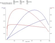
Hey before you go... Im only running 100% Im afraid of anything over. I blew the last powerstage design (4110 18 fet) simply from going to 110% from 100 % at 150 phase amps.

How about this... Have a erpm set point where the trapaziod starts. IE lookign at my graph if you want more speed start it at say ~65km/h and scale it over a rpm range.
And yes Im realy happy with this. I still have some tweeking but its getting there. I know the sag is partialy in the batterys but also in connectors. I need to spend some time making some better connections. As soon as some more lipo is avalible it will be on order. IM stocked :) Now to figure out how to insure this thing.
 
If you're afraid of going over 100%, try 12s lipo and slowly go over 100% while keeping an eye on the waveforms...

There's no rpm control over when the trapezodial starts. The way it works is, the chip basically raises or lowers
the amplitude of the output sine waves to achieve the phase current the rider sets with the throttle. The 100%
setting means that the chip won't raise the output voltage any further than so and so much. There's no link with the rpm,
it all depends on the throttle. When the chip won't raise the voltage anymore, with an increase of speed / backemf the
current / torque starts to drop off. By going to more than 100% the chip will squeeze a bit more voltage out of the controller,
meaning it will maintain the higher current / torque for longer...

When you blew up the last time, did you have the spikes under control like you do now ?
 
Lebowski said:
If you're afraid of going over 100%, try 12s lipo and slowly go over 100% while keeping an eye on the waveforms...

There's no rpm control over when the trapezodial starts. The way it works is, the chip basically raises or lowers
the amplitude of the output sine waves to achieve the phase current the rider sets with the throttle. The 100%
setting means that the chip won't raise the output voltage any further than so and so much. There's no link with the rpm,
it all depends on the throttle. When the chip won't raise the voltage anymore, with an increase of speed / backemf the
current / torque starts to drop off. By going to more than 100% the chip will squeeze a bit more voltage out of the controller,
meaning it will maintain the higher current / torque for longer...
But would it not make sense to add a rpm based starting point. I meen if you have say 300 phase amps limit and you are under a phase amp limit untill say 3000 rpm then if you add cliping to anything below 3000 rpm you will just make it more efficient. Or are you saying it will still try to use FOC and the center aligend pwm to feed the power in at the center of the back emf to make the motor the same efficicncy up to say 3000 rpm where there is no longer a limit on the phase amps?
When you blew up the last time, did you have the spikes under control like you do now ?
No I did not scope it properly. I did not understand what the spikes were.
 
You can hit the phase amp limit with the motor at standstill. So its not like you say, you're not under the
phase amp limit until such and such rpm. The controller will try to achieve the throttle indicated
phase amps independent of rpm.

Trapezoidal waveforms will reduce the efficiency when compared to sine waveforms, so you want to
postpone using trapezoidal until it's the only way to achieve the phaseAmps.
 
Some things which I've found raise efficiency / speed:
- short deadtime. Long deadtime reduces the voltage the controller can provide, especially when limiting amplitude to 100%
- higher PWM frequency gives less current ripple and reduces losses in the motor (but increase them in the driver stage / output stage)
 
Lebowski said:
Trapezoidal waveforms will reduce the efficiency when compared to sine waveforms, so you want to
postpone using trapezoidal until it's the only way to achieve the phaseAmps.
Yes this is what I am saying.
 
Lebowski said:
Some things which I've found raise efficiency / speed:
- short deadtime. Long deadtime reduces the voltage the controller can provide, especially when limiting amplitude to 100%
- higher PWM frequency gives less current ripple and reduces losses in the motor (but increase them in the driver stage / output stage)
I will spend some time doing some quick testing but I think the dead time at ~1800ns starts to raise the battery current so I set it to 2100ns to be safe.
My motor and controller are about equil in tempature when done a ride. But I have 2 fans built into my controller moving air over the heat sink all the time.
So I would think the controller is producing more waste heat. I will buld up my next one with faster switching to help reduce the heat.
But I will try a dyno run with 30 khz and one with the current 20 khz pwm and compare them to see. I will try to have a R&D Dyno day or evening soon.

Thanks Lebowski. I could have not got this far this fast with out you. I will keep making things better on my end and you keep adding cool stuff on yours and we will see where this goes. BTW. the $1000+ sevcon would be is it 480 phase amps and ~120v fully charged with erpm limit at 400hz so 2400 rpm and... BIG AND the last I have seen sevcon can not run low inductance motors.
 
I'm still wondering whether it's your inbetween stage that's causing the long deadtime, and whether you actually need this stage. Maybe you'd be better off without it.
Can you post a (readable) schematic with resistor / capacitor values ?

When you're doing the dyno-ing, please also a comparison run with / without FOC.
 
Lebowski said:
I'm still wondering whether it's your inbetween stage that's causing the long deadtime, and whether you actually need this stage. Maybe you'd be better off without it.
Can you post a (readable) schematic with resistor / capacitor values ?

When you're doing the dyno-ing, please also a comparison run with / without FOC.
There is a zip file posted in the same post with the screenshot a couple pages back. I will try to post it againg later.
 
aplause.....aplause...aplause!
how long befor the Controller building for Dummys starts? :mrgreen:

huge thumbs up Arlin.
 
That bike looks on the small size. What is the next size up, a 125 CC frame ??

You da MANNN, Arlo. 8) 8) 8)
 
Thanks guys I will put a dummies guid together soon and I will post my schematics so all can try to copy as I develop this.
Harold this was origanly a Yamaha YSR 50. I also have a 1987 CBR 250r for a conversion if I can make enough power with colossus.
 
I'm very curious to see the schematics of the current setup. Especially since the
gate diodes in the schematic of a few pages ago are in reverse and would actually
make it very difficult to keep the transistors off. With the way they're in that schematic
you're set for low-gate-resistor turn on and high-gate-resistor turn off.
 
Lebowski said:
I'm very curious to see the schematics of the current setup. Especially since the
gate diodes in the schematic of a few pages ago are in reverse and would actually
make it very difficult to keep the transistors off. With the way they're in that schematic
you're set for low-gate-resistor turn on and high-gate-resistor turn off.
I have not updated the SCH file. I had them backwards on the SCH file.
I have the diode on the low side to help turn the fets off and no diode on the Low side.

So 15 ohm resistor feeding 3 fets on the LOW side and 15ohm parallel to a diode folowed by a 1 ohm resistor feeding 3 fets on the Hi side.
 
what kind of diode do you use, can you give a type nr ? I'd like to look up the datasheet to check the internal resistance...

But, 15 ohm to feed 3 FETs... This means that with 15V gate drive voltage you only pull 1 Amp (peak !) from the
gate driver.. an IR2186(4) can deliver 4 Amps, meaning you don't need all that stuff in the middle. You can take
out the 4 small fets and drive the big FETs directly, the 15 Ohm gate resistance will limit the current to well within
the 4A of the IRS2186. The will greatly reduce your deadtime !
 
Back
Top