ASI BAC8000 help wiring

GianlucaO

10 W
Joined
Sep 23, 2019
Messages
65
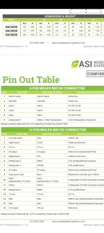
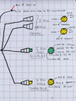
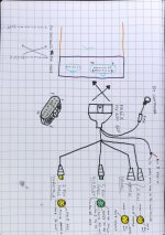
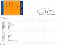
Hi, I bought an ASI bac8000 complete with wiring and display some time ago. I mounted everything but there is no response from the accelerator and the red LED was flashing. Now the display and the red LED do not light up anymore. I found the PIN out of the controller and with a multimeter I created this drawing of the electrical diagram provided by the seller. The IGNITION and Display one seems correct to me but the Brake and Throttle one does not seem correct to me. Can you help me to solve it? I hope the controller was not damaged by a wiring error that I did not make.

Thanks
 

Attachments

  • Screenshot_2025-04-12-18-31-23-531_com.adobe.reader.jpg
    Screenshot_2025-04-12-18-31-23-531_com.adobe.reader.jpg
    767.3 KB · Views: 27
  • Screenshot_2025-04-17-12-10-53-348_com.whatsapp-edit.jpg
    Screenshot_2025-04-17-12-10-53-348_com.whatsapp-edit.jpg
    554.9 KB · Views: 23
  • IMG_20250416_143901.jpg
    IMG_20250416_143901.jpg
    3.6 MB · Views: 20
Hmmm, seems like there is some weird stuff there. There should be a ground going to the throttle. What display did it come with? Strange that there are two 12V lines going to it.
There is a GND ground (PIN 15 of controller) to the display, two 12v PINs (PIN 16 of controller), TTL RX (PIN 13 of controller) and TTL TX (PIN 3 of controller). The problem in my opinion is the wiring to the Throttle connector and Brake connectors.
 
hi, the problem of my asi bac8000 is on the 5v line (pin 4 and 8), short with gnd. so i will have to have it repaired. what could be broken inside? do you know what is the electronic part or component that manages +5v?

for the short time it worked the display showed a "throttle voltage out of range" error but nothing was connected except the display and it showed a throttle voltage of 0.06v and a vendor set range of min 1v, max 4v

thanks
 

Attachments

  • FB_IMG_1745773622113.jpg
    FB_IMG_1745773622113.jpg
    80.5 KB · Views: 5
Hi GianlucaO,

Are you testing for the 5vdc output with your bad wiring connections disconnected? I.E. It looks to me like Bad pin terminations for Both brake and throttle wiring, well ok, all of them... or have you corrected these from what you show in your diagrams?

I'd like to help if I can.

What is your display make and model?

Regards,
T.C.
Yes, disconnected cables. Yes the wiring was poorly produced by the supplier. The display is always produced by him I don't know if it has a brand, at startup it shows the Bull Bike logo of the seller.
 
hi, the problem of my asi bac8000 is on the 5v line (pin 4 and 8), short with gnd. so i will have to have it repaired. what could be broken inside? do you know what is the electronic part or component that manages +5v?

Often the last step down component in the circuit is a LM78L 5 vdc regulator IC or similar.
https://www.ti.com/lit/ds/symlink/lm78l.pdf?ts=1745844354444

Did you check for 12 volt present on pin 16?

Looks like Bull Bike uses this model display…
https://e-racing.world/wp-content/uploads/2022/11/750C-display-low-voltage-version.pdf
APT 750c display for ASI controllers

Controller reference:
https://www.acceleratedsystems.com/...r_controllers_spec_sheet_w_pin_out_table2.pdf
 
5qw6WYJ.jpeg
 
Back
Top