*** Attention FET driving smart guys*** I need help. 300a RC

Joined
Oct 28, 2008
Messages
14,539
Location
Manhattan Beach, CA, USA
I know a few of you folks are damn slick when it comes to working out knowing what it will take to switch certian banks of FETs.

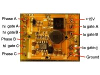
I think the photos explain everything well enough. I just gotta know what I need to do to beef up the FET drive signal enough to switch these 18 x IRF4110's from the K-force RC brushless controller, which doesn't suck or loose phase sync. Yes, those are mounted in a way so that every package is electrically isolated from the heat sink.

I will have the high curent and switching wires finished on the FET bank soon. I just need to know how to beef up the signal enough to drive it with this controller. Thanks!

-Luke

kforce.jpg


chipu.jpg


procboards.jpg


underprocs.jpg


oldfets.jpg


newfetss.jpg
 
Also, what size resistor do you recomend for connecting each gate lead off the IRF4110's with?

And is this as simple as just stacking each of the S2003 chips to be like 3-4-5-6 high or however many it needs? Because that would sure make it an easy fix :)

Also, I need make sure the power supply can handle 90vdc input, when it's only made for 25vdc. Just a simple bucking Vreg set to 25vdc to power the input to the board? Will the back EMF be high enough to fry this thing? I'm retarded about this stuff :(

-Luke
 
Hmmm...
The S2003 gate driver has the following ratings:
VOFFSET 200 V max.
IO+/- 130 mA/270 mA
VOUT 10 V - 20 V
ton/off (typ.) 680 ns/150 ns
Deadtime (typ.) 520 ns
The full datasheet is here: http://www.irf.com/product-info/datasheets/data/irs2003pbf.pdf

A typical connection diagram looks like this:
S2003 gate driver connections.jpg


This means that one of the pins is connected to the battery + input on the existing board. This might be hard to isolate.
I think you'd be better off finding a different (but similar) gate driver chip and pull the signals going to the inputs of the existing ones. I'm sure we can find something suitable. You could leave the existing ones installed, as they won't have any load. If I re-read the app note on driving gates (also on the IR website) we can calculate the gate resistors for your case. Just swagging it, I'd say somewhere around 22 ohms. If you get a beefy enough gate driver chip, you should be able to drive all the gates off one chip (per phase). I know an IR2101 will drive a pair of 4110's OK with 10 ohm gate resistors. That's what I have in my Crystalyte controller.

Yes, you'll need some kind of voltage regulator to power the processor and drive the low side gates. I think the existing regulator will be OK to keep as long as you pre-regulate the input.

What is the existing controller's input voltage range?
 
Also, each phase wire will have a path through some resistors back to the processor for back EMF detection. These resistors may need to be increased to operate at a higher voltage, but maybe not. It would be good to trace the board and see what the existing resistors are.
 
This means that one of the pins is connected to the battery + input on the existing board. This might be hard to isolate.
that Vcc is actually 12V bootstrapping supply that comes from this:
=======
ST662A Series
DC-DC Converter For Flash Memory Programming
Output voltage: 12V +/- 5%
Supply voltage range: 4.5V to 5.5V
Guaranteed output current up to 30mA
Very low quiescent current: 100mA
Logic-controlled electronic shut-down: 1mA
Only capacitors needed (no inductor)
=======
watch out for this charge pump 12V supply. that's why this ESC can work down to 5.6V as indicated on the shrink wrap.

now you have two things to consider:
1. bootstrapping supply strength -> might have to enlarge the charge pump caps so that it could supply a bit more for the bigger gate turning current
2. for S2003, if you dont want to attach external bipolar transistors and hack, the simplest idea i could come out is to stack chips.

but you are still constrained by the max supply voltage, this you have to isolate the battery voltage from the control board supply...a bit more challenging if you wanna go beyond the rated voltage.


-george
 
Here's the datasheet for the old FETs:
http://www.irf.com/product-info/datasheets/data/irfh7932pbf.pdf

My guess is they are driving the gates with 5v.
It would be good if you could measure the Vcc pin on the gate driver when it's powered.

The gate drivers look like they could power 4110s if they can do the old ones, but 4110s better have more like 12v for gate drive.

If you stacked the driver chips, I think you'd want to keep the output pins separate, and run those to separate FETs. This would prevent shoot through in the drivers if one switches slightly faster than another one.

If you can post a nice pic of the backside of the board that has the gate drivers on it, I can almost trace it out from the pictures (very nice pictures, btw)

Then you would also need a voltage regulator that handles the new, higher voltage and steps it down to something the regulator built into the controller can handle. Maybe 12-15v or so. This is pretty easy.
 
I think this approach might work well. We've seen similar approaches work in the past:

1. Go to the graveyard and dig up some parts doners.
2. Cut up the corpses and take the best parts from each (use the smartest brain, strongest body etc.)
3. Put the good pieces together
4. Hook up some wires and pump in a bunch of electricity
5. If it starts moving, stand back and cry "It's Alive!"
Frankentroller1.jpg

Now get to work Igor :twisted:
 
Fetcher- Maybe this can help?

http://img55.imageshack.us/my.php?image=underproc.jpg

http://img23.imageshack.us/my.php?image=procboard.jpg

I can take more photos if you need anything.


Georgeycc- That glue is artic alumina insulating thermal epoxy. I have all ready tested poking a 110vac lead to the tang of each FET after checking with a meter, and nothing jumped through the thermal epoxy. I also have artic silver, but it has a little worse electrical insulating properties. It's somewhat time consumeing to work with opposed to other FET mounting methods, and pretty awful if you need to change parts, but it performs very well.


I need some advice on what I need to do to make the control circuit able to deal with 90vdc input voltage. I'm assuming that they need to share a common ground connection for the back EMF signal to be correctly read by the controller? Does this mean I could simply setup some bucking voltage regulator circuit to feed power to the controller board, run a common ground with FET supply power, make a few stacks of S2003 chips, a load of cap, and on my merry way?
 
OK, the pics are good.

One problem is the board has multiple layers, so it's hard to trace the middle layers. It also looks like you might have ripped the through plating out of a couple of holes, which may or may not cause a problem.

Does anyone know what the chip resistors marked "O1C" might be. I've never seen letters on them like that. It would be helpful to know what the resisistance of those might be. You could try measuring across a few of them with an ohmmeter. What's an O1B too?

As far as overall topology, Yes, you make the ground side common to everything, and you need a voltage regulator to drop 90v or whatever down to something in the specified range for the original controller. I'd suggest around 15v, then feed that to the B+ pin on the controller board. From there, it's possible to see which pins are the gate drive and phase sensing, but I'd like to see what the sensing divider resistors are.
The power stage is built just like the schematic given for the gate driver. I think the stock drivers could run pairs of 4110's (and with that humongous heat sink, that should be good for over 100A). To drive more FETs, you could stack drivers, but run the output pins separately to the other FETs. I would not try this until you are sure you need to. I'd try it with just the stock drivers first.

Stay tuned. When I get a chance, I'll try to map out the board connections for your.

BTW, how much does one of those ESC's cost? I suspect many of the cheaper models use the same 'brain' but just a weaker output stage. Maybe a 20A one might work just as good, for example.

Do you have an oscilloscope you can check the gate signals with?
 
i have a ebay "mystery pentium 100A" controller in hand so i also took a look of it's make. interestingly i found that how they rate the current capacity is very different to the Turnigy ones.
for this Turnigy 40A, it has two mosfets per phase, per switch. each mosfet is rated "absolute max 20A @ 70 deg C", and the controller is rated as 40A
this pentium 100A has 6 mosfets per phase, per switch. each mosfet is rated as 94A max rating (Fairchild FDD8896. 25deg C), so that's about 550A per switch capacity and this is rated as 100A only.

any comments on the ratings?
 
Here's what it looks like so far. Assume a 90v to 15v regulator.
The power stage goes just like it shows in the datasheet diagram. The gate resistors are already on the controller (33 ohm). The connections are based on a fair amount of guesswork, so it would be best to trace some of the connections with an ohmmeter.

All the high side FETs have one connection to the battery + wire
All the low side FETs have one connection to the battery - wire
The phase wires go to both high and low side FETs

It would be good to verify which gates go to which pins, as these connections are not visible. It would be bad if you mix up the gate drive signals.

Turnigy connections.jpg

Then make the connections to the power stage like this: Each FET can actually be a pair of them in parallel. All the ground and B+ connections are parallel.

I would strongly suggest trying this with pairs of 4110s before attempting to add more gate drivers. Learn to walk before you run.
Turnigy power stage.jpg
 
Here's a schematic from something that is probably quite similar to the Turnigy controller.

It would be good if you could measure the voltage on pin 1 of the gate driver when it's powered up. If you only have 5v, that won't be enough for 4110's. You could use a small power supply to feed 12-15 volts into it for testing.
Sensorless Controller2.jpg
 
How is it I just stumbled upon this?
 
Arlo1 said:
How is it I just stumbled upon this?


lol, I don't know. Re-reading this, I was SOOOO clueless about clever controller design just a year ago. :)
 
fechter said:
Are you going to hook that thing up to a bank of those Ixys modules? :twisted:


lol, hell no! I'm so done with RC controller "brains". lol Sensorless is great for running a prop, but has no place trying to start motors under load from zero RPM.
 
Back
Top