Avoiding spot welding - Using magnets?

Joined
Aug 24, 2020
Messages
5
Hi all,

Looking to build my first pack - a 20S 15P for an e-kart build. I'm using Samsung 20S 30A cells, since they maintain their voltage well under load and don't get very hot under continuous load.

I'm desperately trying to avoid spot welding. Tell me to get over myself, but i read a quote from the zero motorcycles battery guy that basically said 'however well you spot weld' damage can still be done to the interior of the cell.

So, i've been around the houses and even considered using a high tensile strength thread to evenly tension copper bar across the ends of cell groups (yes i know - it's not a good idea)....

... I've come back to this article from spinningmagnets, which mentions using Neodymium button magnets.
https://www.electricbike.com/introduction-to-battery-pack-design-and-building-part-3/

Has anyone tried this/got any practical experience??

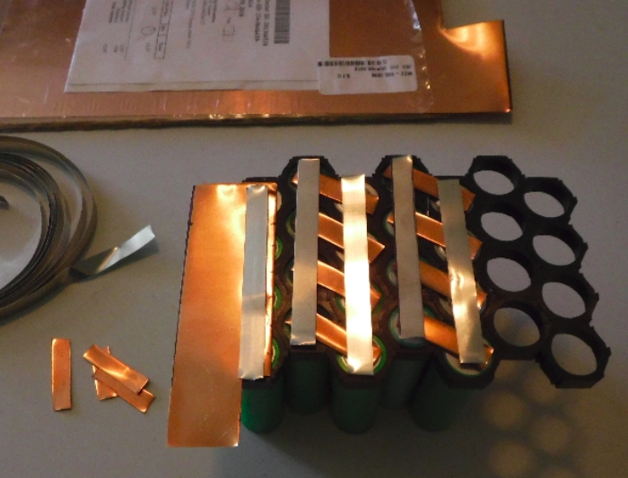
Rather than just laying on some copper sheets and plonking on magnets, i was thinking that i'd:
1) screw the magnets to a ~5mm hard plastic sheet (spaced to meet the cell ends)
2) lay over copper sheet where i want to make the connections
3) lay the cell holders on top of the copper
4) put the cells in
5) do the same in reverse at the other end

Once complete some screws could be inserted right through the back between the cells to secure the 2 plastic sheets.
So, i'm pretty confident the magnets won't move, but i'm hoping you all will now tell me about all the stuff i didn't think of?

Best,

Matt
 
There are multiple threads on this subject with pretty complete build methods, several variations.

Early zero motorcycles literally used rubber bands.

Usage reports with magnet packs indicate decent functionality but a few issues with vibration, however these are easily fixed.

Then there are the pressure methods, poron foam being the best "spring", check out well-engineered kits from NESE, user Agniusm. Pay special attention to the testing apparatus which continually measured output while mounted in something which resembled an industrial paint-shaker.

There is also my own proposed design utilizing dimpled copper strips with magnets in the dimples and the whole thing compressed with poron foam. Likely not practical but ya never know.

Whatever you choose, do NOT buy a Vruzend kit as these are a poorly engineered piece of crap relying on friction alone and if you buy one I will shame you for a fool when you come back for help making it work. Thank god Eric doesn't sell these or no one would ever know what crap they are.

Edit - suggested key words for search function "no weld", "solderless"
 
You can use any method you want on the positive tip. Spot-welding buses wont hurt it at all. You can solder to it also, and if heat makes you nervous, you can solder just a thin fuse-wire onto the positive tip, which can be done so fast and so easily that there is no concern about heat. You can even spot-weld a fuse-wire onto the positive, if you like.

The negative end is sensitive to heat, so that's where you need to do something creative. I still like the idea of magnets, but I simply haven't had the need to build a battery since I came to that conclusion (I owned three packs at the time, and they all still work fine).

Consider building a small 4S / 12V pack, so the prototype is a small investment until you're happy with the result. I'd recommend some type of cell-holders to form a rigid skeleton, but when the cells get warm, they will expand slightly. Not much, but I think there needs to be something to allow for that. One option might be to back-up the magnet with a sheet of Poron foam. You could use super-glue to attach the magnets to the bus material so the magnets cannot move around.

Another option for the parallel buses is to put nickel on top of the magnets. I don't know if that's a good idea, but the low conductivity of the magnets won't hurt the parallel equalization of cells. Only the series current needs to be directly attaching the cell top the bus.

For parallel, you could also solder a thin wire across the series bus strips. Many options and choices...

If you buy magnets with a hole in the center, and later you decide to NOT use the magnets in the battery-pack build, those magnets are really handy for holding up tools in the garage and a variety of other clever and fun gadgets.
 
spinningmagnets said:
when the cells get warm, they will expand slightly. Not much, but I think there needs to be something to allow for that.
So the expansion is along the length if the cylinders?

Or also the circumference?

 
The expansion of circumference is negligible and it can be taken up my stretch in the materials of the framework. Meaning, it wont cause cracks in the framework, or cause issues with contact between the cells and the magnet/copper-buses.

I don't know how much the length would expand, maybe only one or two millimeters at worst? This is another reason the cells should never be allowed to go over 140F.

I imagine it's going to be necessary to have two hard side-panels as the outer layer. so, within the context of having the cells in the popular plastic cell-holders, what are the options? The copper strips absolutely have to be laid touching the cell-tips to reduce voltage sag. I would put the magnets directly on top of the copper series strips, to provide the strongest holding power they are capable of. The parallel connections can be handled a variety of ways.

One concern posted in the magnets thread is that the magnets want to move around. That was the reason I mentioned the magnets with a hole in the center. However, if you want to glue the magnets onto the series strips, perhaps a solid disc magnet would have a more solid connection to the glue, and a stronger magnetic hold onto the cell?

This leaves how to connect the two side-panels, but regardless of the connection options, I like the idea of thin foam between each hard side-panel and the pack. If using foam, Poron is the best.
 
i agree, you need something to keep the magnets from moving but i think you also need something to keep the copper from moving.

if the copper moves slightly while discharging youll see a scratchiness in the discharge line of a chart while testing.

i dont know what will happen if you have 4 cells on 1 sheet of copper, may not go well with a high amp battery pack.

i think you also need flexibility in the copper between cells, if there is a twist or a flex between any of the cells in the group or series youll lose connection. with the copper slug tape all the cells can move independently with out the magnet being torqued off the cell end

you dont want a big magnet either, bigger isnt better and neither is stronger. you get into n50 range of magnets and they cant handle the heat.

grin technologies did a test on magnets for their motors. there is a sweet spot with magnets and heat. i think the magnets im using are the same N-rating as what is in their motors. actually im using n42 and grins using n40 in the motors

https://www.ebikes.ca/product-info/all-axle-hub-motor.html
 
This is one of the options I drew in the magnet thread. The common plastic cell-holders have slots that would hold the strips inline, but between the two cells in series, I suppose you could add a "crinkle" to act as an expansion joint.

"Magnets holding copper bus onto cell, no-weld no-solder"
https://endless-sphere.com/forums/viewtopic.php?f=14&t=104405
file.php


and another option with no nickel, since copper sheet is cheap in bulk.

file.php


Here are the plastic cell holders below, I mentioned. They have recessed slots for the buses, so any panel laid across the face of the block of cells will not touch the buses. In the pic below, the copper is touching the cells for the lowest resistance and lowest voltage-sag, but the nickel above is required for "nickel/copper sandwich" welding. With magnets, no nickel is required.

BatteryCopperSeries1.jpg


Someone could argue that if I believed so strongly in magnets as a bus connection (instead of welding), then I would have used it by now, but...as I stated, I have three awesome 14S packs, no need for a fourth. When I retire, I plan to make a few packs for things like 24V kiddie cars, converting from lead-acid to lithium. When I retire, also plan to make at least one 14S triangle pack with the ability to slip-in loose cells, but I just don't have the time right now. I'll build it for an article and then sell it at cost, because I have too much clutter piled up as it is now.

Another option is the conductive grease that LFP developed. A tiny dab between the cell and the copper bus eliminates any oxidation that might occur (shiney copper turns brown)

"Conductivity improving grease project"
https://endless-sphere.com/forums/viewtopic.php?t=61542
 
i agree with that style holder

but not so much this style

Lyb6VR6.jpg


if a battery doesnt have an air space around it it will drive the cell temperature up. unless youre trying to increase pack temperature. ill go find a post i made and put link here

https://endless-sphere.com/forums/viewtopic.php?f=14&t=106550#p1562176
 
I agree with air circulation around cells. It doesnt seem to be a huge concern in the ebike community, based on how many still build with hot-glue.

If you use high-amp cells, and a large enough P-group, then pulling average amps will result in a cool-running pack. Sadly, many still pull high amps from a small pack, and then wonder why the hot cells die in just a year.

Tiny quiet 48V computer server fans are cheaply available. I can see having two, one pushing air, and the other pulling.
 
Hi all,

Thanks so much for the replies and apologies for covering old ground - the search terms and links have been great inspiration and i'm refining my idea. Goatman - loving your work.

Talking about cell arrangement (rank & file vs honeycomb) - i'm leaning towards R&F because mechanical sympathy tells me to go with the bigger air gap. That said, this cell discharge test shows max 35*C at a 30A discharge, making me think that perhaps temperature won't be so much of a problem with these cells?

Third chart down:
https://lygte-info.dk/review/batteries2012/Samsung%20INR18650-20S%202000mAh%20(Cyan)%20UK.html

Perhaps honeycomb holders on the cell ends would be ok, but on a hot day at the track these temps might go up to something more worrying though...

@Spinningmagnets - thanks for the thought about the test pack. I actually have 4 cells already (but i'm sadly lacking a charger and any means of testing them!).

I'll take a look at chargers and try'n understand what constitutes a test rig. Ideally i can source/make one that can deal with my 4S test pack and the 15P20S finished pack. Although as always, any steering is appreciated.

Matt
 
theres different thickness of slug tape .02 and .05

if you do play with these at higher than 10amps id increased the size of hole in magnet and maybe go a little thicker to maintain the pull strength.
and keep the edge seam up and not down, if youre pulling high amps, current will try to pass through the conductive adhesive and the discharge graph line will get scratchy

fSm2qGi.jpg
 
Back
Top