Hi,
I've learned a lot here, so want to give back with this 13S1P DIY build - in case someone else might be wondering if this is feasible
I have a 750 Wh commercial pack, great for long hauls, but a pain in the back for those short 20 odd km rides I end up doing a lot all the year round (also commutes). Pain in the back, coz my bike is a really funny shape, leaving no easy space to fit a pack to the frame (it is a so called "Uber V", ie a 25 yo Cannondale "Super V" modified with a lefty fork, and a Scalpel rear triangle so disk brakes can be fitted all round, and finally a rear hub brushless motor + 25A controller + cycle analyst):
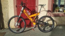
So the idea was to see if I might get enough juice from a single string of cells, such as 13S1P to reach the max 48V my controller can deal with. And 1P only because the only place that's not in the way, is in the gap between the front wheel and under the main diagonal tube, which is so oversized (70mm diam) that cells could fit orthogonally and not stick out. This 500x70x40mm space could fit 13 cells side by side followed by the BMS.
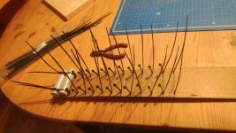
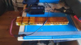
Problem is getting enough amps from 1P only, 25A is hard on a cell, so I turned to the slightly larger 21700 Molicel P45B that seemed to pack a punch, with up to 30A continuous discharge, so should handle my controller's max 25A, yielding in theory 1200W (more than my hefty 750 Wh that's just 36V). With a capacity of 4.5Ah x 48V = 216 Wh, which should push for the entire length of my routine 20-30 km trips in hilly Provence (usually 5-8 Wh/km). I opted for neodyme magnets to press 0.1mm copper bus bars onto the cells, because I did'nt have a spot welder, and didn't want to loose any of each cell's capacity during welding, plus I might want to experiment several shapes for the pack, plus it is easier to replace a bad cell. Here's a few pics of the making :
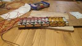
The BMS is a JK Smart Active Balance BMS BD4A17S4P - (8S - 17S) - 40A:
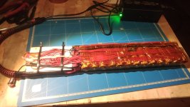
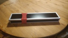
The case looks fine, and could be run over by a bus, but I'm not satisfied as it is heavy, and also I made it a little too wide and high. It is made of aluminium/plastic sandwich sheets (al-plastic-al, 3mm thickness) with aluminium angle rails with 3mm grooves, everything glued apart from one end cap, and top panel which slides out. The pink shrink wrap was a test.
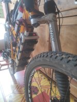
I am happy to report that the pack behaves exactly as planned: 24.25 A according to Cycle Analyst (over 1100W), and over 180 Wh with a 4.17-3.15V discharge (I don't need any more, and don't know how bad it is for the cells to go further down in voltage). On a normal ride the temp probe in between the cells doesn't go much above 30°C. When I emptied half the pack in a straight continuous 400m climb, temp peaked over 40°C, so no issues there.
In fact the pack has so much juice, it nearly knocked me off the bike on the first trial. I don't need that much, so I'm gonna lower the throttle max amps
Also the bike is far better balanced now, it used to be back heavy with that hefty hub motor, much better grip at the front, much less tendency to do wheelies in steep climbes. And oh boy is it nice to forget that back pack, and have free shoulders whilst riding
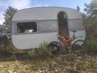
The pack's nickname will be "Into the wild" :
I've learned a lot here, so want to give back with this 13S1P DIY build - in case someone else might be wondering if this is feasible
I have a 750 Wh commercial pack, great for long hauls, but a pain in the back for those short 20 odd km rides I end up doing a lot all the year round (also commutes). Pain in the back, coz my bike is a really funny shape, leaving no easy space to fit a pack to the frame (it is a so called "Uber V", ie a 25 yo Cannondale "Super V" modified with a lefty fork, and a Scalpel rear triangle so disk brakes can be fitted all round, and finally a rear hub brushless motor + 25A controller + cycle analyst):

So the idea was to see if I might get enough juice from a single string of cells, such as 13S1P to reach the max 48V my controller can deal with. And 1P only because the only place that's not in the way, is in the gap between the front wheel and under the main diagonal tube, which is so oversized (70mm diam) that cells could fit orthogonally and not stick out. This 500x70x40mm space could fit 13 cells side by side followed by the BMS.
Problem is getting enough amps from 1P only, 25A is hard on a cell, so I turned to the slightly larger 21700 Molicel P45B that seemed to pack a punch, with up to 30A continuous discharge, so should handle my controller's max 25A, yielding in theory 1200W (more than my hefty 750 Wh that's just 36V). With a capacity of 4.5Ah x 48V = 216 Wh, which should push for the entire length of my routine 20-30 km trips in hilly Provence (usually 5-8 Wh/km). I opted for neodyme magnets to press 0.1mm copper bus bars onto the cells, because I did'nt have a spot welder, and didn't want to loose any of each cell's capacity during welding, plus I might want to experiment several shapes for the pack, plus it is easier to replace a bad cell. Here's a few pics of the making :


The BMS is a JK Smart Active Balance BMS BD4A17S4P - (8S - 17S) - 40A:


The case looks fine, and could be run over by a bus, but I'm not satisfied as it is heavy, and also I made it a little too wide and high. It is made of aluminium/plastic sandwich sheets (al-plastic-al, 3mm thickness) with aluminium angle rails with 3mm grooves, everything glued apart from one end cap, and top panel which slides out. The pink shrink wrap was a test.


I am happy to report that the pack behaves exactly as planned: 24.25 A according to Cycle Analyst (over 1100W), and over 180 Wh with a 4.17-3.15V discharge (I don't need any more, and don't know how bad it is for the cells to go further down in voltage). On a normal ride the temp probe in between the cells doesn't go much above 30°C. When I emptied half the pack in a straight continuous 400m climb, temp peaked over 40°C, so no issues there.
In fact the pack has so much juice, it nearly knocked me off the bike on the first trial. I don't need that much, so I'm gonna lower the throttle max amps
Also the bike is far better balanced now, it used to be back heavy with that hefty hub motor, much better grip at the front, much less tendency to do wheelies in steep climbes. And oh boy is it nice to forget that back pack, and have free shoulders whilst riding
The pack's nickname will be "Into the wild" :


