• Hello ES! We could use some help to get us past the finish line on building the new knowledgebase for the forum.
    Can you donate? Please see our fundraising page. Thank you!

Bafang g33 bms battery wire

aca

New here
Joined
Feb 6, 2026
Messages
7
Location
Belgrade
Hello. I have a bike with bafang g33 250w uart and it has an aftermarket battery with only two wires positive and negative. The original battery had positive negative and 4 more thin wire for communication with bms i guess whitch are now left isolated.
The problem i have with my bike that torque sensor and pedal assist are not working. Do you think its not working because of those 4 wires that have nowhere to connect and is there any way to bypass that. I tested tourque sensor in software and its changing voltages when spinning but PAS is not working. Bike also works on walk mode and on throtle but no pedal assist and has no error code...
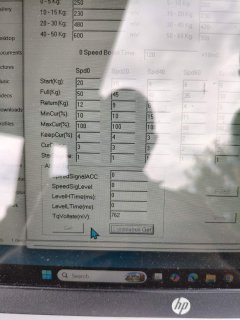
 
In software controlerst_torque i can see only tourque volt changing but everything else is at zero. Does anyone know if i can fix this?
 

Attachments

  • IMG-fcac017aad7a3c220e6b6a908ad05690-V.jpg
    IMG-fcac017aad7a3c220e6b6a908ad05690-V.jpg
    242.3 KB · Views: 3
Sure it is G33 and not G330 or G332?
Anyway as far as i know those 4 thin wires can be left unconnected and are most likely not the cause of the problem you have.
 
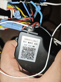
It says g33.250 on controller. I also have a screen DZ40 from AliExpress so it could be that too although walk mode and speed on on screen work. Also when i change pedal assist it changes lower on throtle but pas doesn't work. Although it should work when usb programer is plugged in even without the screen i think.
 

Attachments

  • MVIMG_20260712_165420.jpg
    MVIMG_20260712_165420.jpg
    5.1 MB · Views: 4
Last edited:
That controller looks like it is a M400 UART controller. Fault can be the torque sensor or controller if controller is from before end 2021 and if later then more likely the problem is the torque sensor. But it looks like you changed the wiring and added diodes etc.
 
I was just testing things i didnt add diodes. On the 4 wire connector that is from torque sensor i messure with multimeter a tourque voltage changing from 0.7v to 4.2v and that can be seen in software too, also with multimeter i tested cadence sensor on same connector and its showing 0v than 5v as i slowly spin pedals so i think its ok too but that i cant see in software... Do you know any way i can make sure torque sensor is dead ?

The way i have it working now is according to this video, thats how i connected throttle and it works but i really want to get PAS to work...
 
I was just testing things i didnt add diodes.
At the top of the picture from your controller i can see 2 diodes somehow connected to the blue throttle wire from the 8 pin harness connector.

On the 4 wire connector that is from torque sensor i messure with multimeter a tourque voltage changing from 0.7v to 4.2v and that can be seen in software too, also with multimeter i tested cadence sensor on same connector and its showing 0v than 5v as i slowly spin pedals so i think its ok too but that i cant see in software...
Torque sensor has 6 wires coming out of the motor housing to the controller, 4 in the black connector (gray wire has the torque signal, about 750mV with no pressure on pedals) and 2 more wires in a blue connector, purple and green wire and those 2 have to alternate too just by turning the axle.
I suppose it is the 750mV - after clicking "continuous get" - you can see changing in the software.
Anyway if al wires from torque sensor measure ok then problem is most likely your controller.

Did bike worked normally before you added throttle?

Adding a throttle like in the video but he did not mention how to connect? Maybe at first you made a mistake and caused a fault?
Just wondering If you wanted a throttle why not just bought a 4T1 harness cable? It has besides the display connector also 2 brake and 1 throttle connector..
 
Yes my brother tried something with diodes i don't know what...

I got bike used without battery and screen. I added throttle like the video just connected throttle signal wire to blue wire on white 8 pin connector and got 5v from some other wires. I didn't know 1T4 existed.
Yes i get 750v on continuous get and it changes to 4.2 as i rotate pedals.

Do 2 wires in blue connector need to have 5v on purple wire then turn crank and 5v on green ?
 
The 4 pin from torque sensor, red = 5V and black is ground. Grey wire is torque signal should be 750 millivolt when not moving the axle / pedals. And that torque voltage on grey wire should not go to 4.2 volt by just turning the axle without pressure / force.

With a good one to get it to reach for example 3.5 volt on the grey wire you have to put some serious pressure with your foot on the pedal. Lock the chain / rear wheel or engage brakes and then if you put pressure on the pedal only then the voltage should go up above 750 millivolt depending on how much pressure you give on the pedal.
So if the grey wire already get 4.2 volt by just turning the axle freely by hand that is not good.

White wire from the 4 pin connector = when turning slowly with axle it switches from around 0 volt to 3.8 or 4.8? and back to 0 and so on.

The 2 pin connector: Purple wire switches from around 0 volt to around 4.5 volt? and back to zero and so on when slowly turning the axle.
The green wire from 2 pin connector: When slowly turning the axle, from 0 volt to 3 or 4 volt and back to zero and so on.

The above is from what i found on a note, from a long time ago when i measured a M400 UART torque sensor... So..
 
Between Green wire and ground always 0v when i rotate crank
Between Purple wire and ground changes from around 4.5v and 0v as i rotate crank

4pin connector
White wire always has 4.5v as i rotate crank
Grey wire does go around 3v or or little more my mistake...

I guess its dead... what do you think?
 
Back
Top