Balance Charge or Bulk Charge - 24 Volt 6S4P pack

sonnetg

1 kW
Joined
Jul 25, 2015
Messages
340
Location
Maryland
Hi,
I haven't found any topic related to this, but I am planning on building a 6S S Pack for my 24 volt Ebike Motor. I can use either use a Imax B6 6S Balance charger, but it would be easier to charge them in bulk.

All my batteries are brand new Samsung 18650 25R, so I dont see any reason why I should not be able to bulk charge them with a 25.2 volt Li-Ion charger such this one: http://www.ebay.com/itm/Lithium-Ion...865?pt=LH_DefaultDomain_0&hash=item4ae9e80cd1

I would like to have balance leads to be able to monitor using a Volt meter, but would prefer not to use any Imax or Balance charger hassles.

Any thoughts on this?

PS: I recently purchased Leed Ebike kit, and that also comes with the same bulk charger. There are no balance leads in the battery.

EDIT: I was completely wrong regarding LEED EBike Batteries. All their battery packs does have a built in BMS. Please see Leed Engineer response below.
 
You can readily use RC Lipo charger type stuff for things like this.
But the imax line is not known for it's reliability or accuracy. I would suggest using something like an iCharger 108b+ instead. Protect your investment and all that.
 
neptronix said:
You can readily use RC Lipo charger type stuff for things like this.
But the imax line is not known for it's reliability or accuracy. I would suggest using something like an iCharger 108b+ instead. Protect your investment and all that.

Hi Thanks for your feedback. I will also keep monitor using a volt meter while it's being charged for battery safety so the batteries do not exceed 4.1 or 4.2 volts. I do plan to eventually upgrade to iCharger, but I see so many videos on youtube who are using Imax B6 charger without any issues, so I would like to give it a try first (Actually I had it for years to charge my 6S RC heli lipo packs).

Down the line, I do have a plan to upgrade to a 48volt kit, and the expensive 8S iCharger would be useless, as 13S packs would be the norm.

I plan to use a Bottle/Frame case such as: https://bmsbattery.com/battery-parts/686-bottle-09-battery-case-for-18650-battery-parts.html

Once I have all the batteries in the frame/bottle case, the most convenient way would be to charge them in bulk using a DC charger.

I know balance charging is the best way to ensure the battery life, but do we have anyone on these forum who charges using a bulk DC 13S or 7S charger?

I would be curious to hear their opinions.

Thank you.
 
dnmun said:
how will you know when it overcharges? there is no BMS.

Apparently, the DC power supply has a built in BMS. It probably sees the whole pack as a single battery. I suppose it stops at 25.9 Volt for 7S Li-ion battery. I see these Adapter on Ebay everywhere. There is also a version for 48 volt 13S packs.

I recently order a Battery pack from Leed Ebike, which came with such a basic DC charger. I opened up the battery pack and saw no signs of a BMS.

I am in the process of building my own battery pack, and will take the 7S balanced route with a iCharger 208B (my 6S Imax B6 isn't gonna cut it with 22.2 volts).

It will be a hassle to charge a 7S 25.9v pack or a 14S 52volt Pack (2 x 25.9) if I decide to upgrade to a 48 volt motor in the future, but I will take this route as it is not only safer, but also help detect any issues with the battery as it ages.

There is all-in-one battery pack option if you purchase a 7S or 13S BMS board. These are also found on Ebay, such as this one: http://www.ebay.com/itm/171843467433?_trksid=p2055119.m1438.l2649&ssPageName=STRK%3AMEBIDX%3AIT

I would certainly freak out using such baisc BMS, but I know few youtubers who've successfully done it. These are probably very risky though. You get distracted, and before you know everything will end up in ashes. Li-ion charging is something I dont take lightly.

Here's an interesting article on this: http://www.instructables.com/id/Make-an-inexpensive-Lithium-Ion-Battery-Pack/step6/Balance-Charging/
 
i have about 8 nanotech pouches outside on the sidewalk that are all below .1V.

if the 6S pack has 5 cells charging and one dead at .1V then what is the average voltage on each cell if the charger charges up to 25.2V?

how would you know if the pack a dead cell when you placed it on the bulk charger?
 
dnmun said:
i have about 8 nanotech pouches outside on the sidewalk that are all below .1V.

if the 6S pack has 5 cells charging and one dead at .1V then what is the average voltage on each cell if the charger charges up to 25.2V?

how would you know if the pack a dead cell when you placed it on the bulk charger?

True, but what if you get a set of complete new batteries with the same brand and Mah rating. The chance of a single cell dying could be slim, but I agree with you. If one cell dies, it could damage the whole pack.

I think this is one reason most cheap bike kits or battery packs have a very short life..about a year or so, but if the batteries are taken well care off and charged with a good BMS, it should last a decade or so.


PS: I am a bit disappointed at Leed (http://www.e-bikerig.com/) for taking the easy route. I will contact them soon and request more information on their "Proprietary BMS", because I see no balanced leads coming out.
 
What did you expect from Leed?

BMS the best way to go, then the bulk charger will do er, and the bms will balance as well as other functions.

At the very least, add a jst plug to your pack. Then you could occasionally use a battery balancer discharger to balance, monitor easily with something like a cellog, use the low voltage battery alarms, and even balance manually using an RC charger to single cell charge, or a turn signal bulb to discharge a single cell.

But if you are going to go bareback like that, you want to undercharge slightly, so you have lots of wiggle room to avoid overcharging a single group of parallel cells using the naked bulk charger.

Jst plug for monitoring still a great idea, even on a pack with a bms.
 
You can make 7S system instead of 6S, and then use this two:

http://www.aliexpress.com/store/product/7S-Li-ion-Lipo-Batteries-Protection-Board-BMS-System-24V-29-4V-20A-Continuous-Discharge-350W/313864_32336397316.html

http://www.aliexpress.com/store/product/24V-29-4V-3-0Amp-Li-ion-LiPoly-Battery-Charger-High-quality-E-bike-charger/313864_1253354957.html

Also, you don't need such strong batteries like 25R, you can use something with greater capacity and 10 A max discharge, like samsung 32E or LG MH1, you will have much more capacity.
 
riba2233 said:
You can make 7S system instead of 6S, and then use this two:

http://www.aliexpress.com/store/product/7S-Li-ion-Lipo-Batteries-Protection-Board-BMS-System-24V-29-4V-20A-Continuous-Discharge-350W/313864_32336397316.html

http://www.aliexpress.com/store/product/24V-29-4V-3-0Amp-Li-ion-LiPoly-Battery-Charger-High-quality-E-bike-charger/313864_1253354957.html

Also, you don't need such strong batteries like 25R, you can use something with greater capacity and 10 A max discharge, like samsung 32E or LG MH1, you will have much more capacity.

This would be my next upgrade. I am taking small steps at a time, but thanks for the links. As for monitoring, I could always use something like a CellLog 7M: http://www.progressiverc.com/celllog-8m.html

I am still debating whether to upgrade to 48volt system, which would actually complicate my battery build, charging, packaging, wiring and all, i wont even gain much range, only speed.
 

Attachments

  • celllog8m_e.jpg
    celllog8m_e.jpg
    32.8 KB · Views: 4,387
dogman dan said:
What did you expect from Leed?

Haha...Their battery pack was a bust. They have a two year warranty, and I am sure the batteries will die right after that. I will ask to see if I can get a refund, else I may have to tear it up and add balancing cables for monitoring. I am fairly new to the ebike world, and Leed does offer very simple plug-and-play cabling for the controllers and batteries. I'm pretty sure many vendors probably do the same.

dogman dan said:
BMS the best way to go, then the bulk charger will do er, and the bms will balance as well as other functions.

At the very least, add a jst plug to your pack. Then you could occasionally use a battery balancer discharger to balance, monitor easily with something like a cellog, use the low voltage battery alarms, and even balance manually using an RC charger to single cell charge, or a turn signal bulb to discharge a single cell.

But if you are going to go bareback like that, you want to undercharge slightly, so you have lots of wiggle room to avoid overcharging a single group of parallel cells using the naked bulk charger.

Jst plug for monitoring still a great idea, even on a pack with a bms.

These are some excellent ideas. Thank you.
 
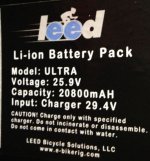
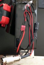
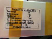
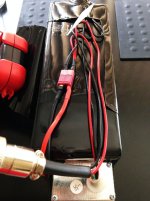
Here's some pictures of my Leed 20Ah 25.9 Volt battery, but I measured it over 29 volts. I dont see any balance leads coming off.

IMG_0408.JPG

IMG_0410.JPG

IMG_0411.JPG

IMG_0412.JPG
 
riba2233 said:
It probably has bms inside.


I sent Leed support the following message below, I am hoping for a resonse soon. Else I will have to tear it down to see.

FYI: Based on the looks of the pack, there is absolutely no space for anything else, except for the batteries. I have attached another image of the battery. If there was a BMS inside, there would be wires visible or at least some bulge instead of a perfect rectangle shape.


###################
Hello Leed support,

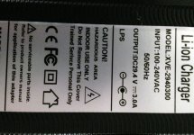
I am very concerned on Li-Ion charging. I am not pleased to find out Leed 7S battery packs are not balanced charged. Out of curiosity, I have opened up the pack, but I see no balance leads anywhere, only a cheap 29.4 volt DC charger.

What if one of the cell goes bad by being overcharged and drops to 0.1V? Does this mean the rest of the pack gets charged over 4.3 volts? That would destroy all the cells.

I am very disappointed at this. Being a US based company, I was hoping for the best service possible. I have spent over $1000 for my first purchase (Order # *****), only to discover Leed has made some really bad shortcuts when it comes to powering the system.

I would like to replace the battery with something that is balanced. Bulk charging can be a fire hazard. Please advise on what I should do.

Regards,

###################
 

Attachments

  • IMG_0407.JPG
    IMG_0407.JPG
    167.9 KB · Views: 4,378
riba2233 said:
I don't know, manufacturers have to use bms to get certificates needed to sell the battery to the wider audience. It can be very flat unit, maybe there is one inside.

I really hope so too. I am waiting to hear back from them. I wasn't sure about the certificate requirement though, but it is nice to know there are such safety measures. Do you have any reference or links to such requirements for li-ion packs?

EDIT: You are probably correct. The BMS must be inside the case. This is such a relief.

Here's the specs I got from their site: http://www.e-bikerig.com/products/ultra-e-bike-kit-250-series-1.html

<snip>
The LEED Ultra+ electric bike conversion kit includes:

250 Watt (250 Series) 8Fun Planetary Motor Hub
2-Year Motor-to-Battery Worry Free Warranty
Complete Wheel Set (Ready to Ride Laced and Trued on Arrival)
20800mAh Samsung 24 Volt Lithium Battery Pack (Includes PCB, BMS and Controller)
Lithium Battery Charger (USA/International 110-240v)
Battery-Motor-Throttle Cable System
Weatherproof Battery Bag
Pressure Grip Throttle
Cabling Zip Ties

</snip>
 
Found an image of the Leed Packet Battery. I think this thread can now be closed. I dont think there is anything such as "bulk charging" Li-Ion batteries. However, I have found few folks in this forum to claim they do not use BMS, so I am not sure how exactly they charge their 13S or 7S packs.

Leed Pocket Battery Juice: http://www.e-bikerig.com/products/PBJ-e-bike-kit-samsung-li-ion-front-wheel.html

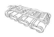
Here's few images of Leed batteries (esp. their pocket battery and how the BMS is hidden away)
 

Attachments

  • PBJ_1.jpg
    PBJ_1.jpg
    103.8 KB · Views: 4,353
  • PJB_2.png
    PJB_2.png
    59.2 KB · Views: 4,353
Hello. I would like to answer the questions regarding the BMS that Leed uses. For the sake of full disclosure, I work for Leed providing engineering support and occasionally work to troubleshoot any issues regarding product failures, which do happen from time to time considering the technology and hardware involved. To clarify quickly here, though it is difficult to quickly explain the tech, all Leed's 250 Series use a BMS in variable VDET operations. This prevents overcharge and disallows a singular cell to supercharge and fully unload. So, allow me to explain the VDET operations that we have built into the BMS for the 250 Series battery systems. Forgive the overkill, but it may be necessary considering the misinformation and disinformation on this thread. I can understand how it gets to that level, but allow me to explain the VDET operations on Leed's BMS quickly regarding overcharging prevention. VDET1n operation or over-charge detectors (n=1, 2, 3, 4, 5) while the cell is charged, the voltage between VC1 pin and VC2 pin (voltage of the Cell-1), the voltage between VC2 pin and VC3 pin (voltage of the Cell-2), the voltage between VC3 pin and VC4 pin (voltage of the Cell-3), the voltage of VC4 pin and VC5 pin (voltage of Cell-4), and the voltage between VC5 pin and VSS pin (voltage of the Cell-5) and so forth for additional cells are supervised. If at least one of the cells’ voltage becomes equal or more than the over-charge detector threshold, the over-charge is detected, and an external charge control Nch MOSFET turns off with COUT pin being at "L" level via an external pull-down resister and charge stops. To reset the over-charge and make the COUT pin level to "H" again after detecting over-charge, in such conditions that a time when all the cells’ voltages are down to a level lower than over-charge released voltage. The output voltage of COUT pin becomes "H", and it makes an external Nch MOSFET turns on, and charge cycle is available. The over-charge detectors have hysteresis. Internal fixed output delay times for over-charge detection and release from over-charge exist. Even if one of voltage of Cells keeps its level more than the over-charge detector threshold, and output delay time passes, over-charge voltage is detected. Even when the voltage of each cell becomes equal or higher level than VDET1 if these voltages would be back to a level lower than the over-charge detector threshold within a time period of the output delay time, the over-charge is not detected. Besides, after detecting over-charge, each cell voltage is lower than the over-charge detector released voltage, even if just one of cells' voltage becomes equal or more than the over-charge released voltage within the released output delay time, over-charge is not released. The output type of the COUT pin is Pch open drain and "H" level of COUT pin is VDD pin voltage. In VDET2n or over-discharge detectors (n=1, 2, 3, 4, 5) While the cells are discharged, the voltage between VC1 pin and VC2 pin (the voltage of Cell-1), the voltage between VC2 pin and VC3 pin (Cell-2 voltage), the voltage between VC3 pin and VC4 pin (Cell-3 voltage), the voltage between VC4 pin and VC5 pin (Cell-4 voltage), and the voltage between VC5 pin and Vss pin (Cell-5 voltage) are supervised. If at least one of the cells’ voltage becomes equal or less than the over-discharge detector threshold, the over-discharge is detected and discharge stops by the external discharge control Nch MOSFET turning off with the DOUT pin being at "L".The condition to release over-discharge voltage detector is that after detecting over-discharge voltage, all the cells' voltage becomes higher than the over-discharge released voltage, DOUT pin becomes “H” level, and by turning on the external Nch MOSFET, discharge becomes possible. The over-discharge detectors have hysteresis. The output delay time for over-discharge detect is set with an external capacitor C1 connected to CT1 pin. If at least one of the voltage of Cells is down to equal or lower than the over-discharge detector threshold, if the voltage of each Cell would be back to a level higher than the over-discharge detector threshold within a time period of the output delay time, the over-discharge is not detected. Output delay time for release from over-discharge is also set internally. After detecting over-discharge, supply current would be reduced and be into standby by halting unnecessary circuits and consumption current of the IC itself is made as small as possible. When a cell voltage equals to zero, if the voltage of each cell is lower than charge inhibit maximum voltage, charge is not acceptable. All the cell voltages are higher than charge inhibit maximum voltage, COUT pin becomes "H" and a system is allowable to charge. The output type of DOUT pin is CMOS having "H" level around 12V of the internal regulator and "L" level of VSS. In VDET3-n or (n=1, 2) excess discharge-current detector or short circuit protector when the charge and discharge is acceptable, SENS pin voltage is supervised, if the load is short and SENS pin voltage becomes equal or more than excess discharge current threshold, and equal or less than short detector threshold, the status becomes excess discharge current detected condition. If SENS pin voltage becomes equal or more than short circuit detector threshold, the status becomes short circuit detected, then DOUT pin outputs "L" and by turning off the external MOSFET, large current flow is prevented. The excess discharge current detector has two thresholds, and each threshold has the output delay time. In terms of the output delay times, the delay time for the excess discharge current detector 2 is set shorter than the excess discharge current 1. The output delay times for the excess discharge-current detectors are set by an external capacitor C2 connected to CT2 pin. A quick recovery of SENS pin level from a value between the excess discharge current detector and short circuit detector threshold within the delay time, may keep the status as before excess discharge current detected. Output delay time for the release from excess discharge-current detection is also set internally. When the short circuit protector is enabled, the delay time is also set. Between the drain of the external FET connected to DRAIN pin, and the drain of an external FET connected to COUT and DOUT, an external resistor should be mounted to release from over-discharge. After an excess discharge-current or short circuit protection is detected, an external FET connected to DRAIN pin turns on and the resistance of release from excess-discharge current, is connected to VSS. After detecting the excess discharge current or short circuit, load is removed and opened, VMP pin level is connected to the VSS pin level, through the pulled down resistor for release from excess discharge, and when the VMP pin becomes equal or less than VDET31×0.75V, the circuit is released from excess discharge or short automatically. When the excess-discharge current is released, the external FET connected to DRAIN pin turns off and resisters for release from excess-discharge current status is separated from Vss. In VDET4 or excess charge-current detector when the battery pack is chargeable and discharge is also possible, VDET4 senses SENS pin voltage. For example, in case that a battery pack is charged by an inappropriate charger, an excess current flows, then the voltage of SENS pin becomes equal or less than the excess charge-current detector threshold, then the output of COUT which an external pull-down resister is connected to becomes "L", and prevents from flowing excess current in the circuit by turning off the external Nch MOSFET. Output delay of excess charge current is internally fixed. Even the voltage level of SENS pin becomes equal or lower than the excess charge-current detector threshold, if the voltage becomes higher than the excess charge current threshold within the delay time, the excess charge current is not detected. Output delay for the release from excess charge current is also set. VDET4 can be released with disconnecting a charger and connecting a load. Though VDET operations are not required, they are important when prolonging a battery system and preventing any damage from continued use. A witting battery operator will not need a BMS in every case, but there are few out there who understand the tech entirely and this is a reason bad information gets propagated quite easily.
 
Hello and welcome to the Forum Ebikecommuter.

Thank you so much for your response regarding this confusion. I haven't yet tested the balance and effectiveness of the BMS on the individual batteries connected in series, but I did measure the whole pack, and the reading came out a little over 29 volts, which is about 4.1 volt per cell connected in series.

I was confused because the battery is rated at 25.9 volts, but the charger specs is rated for 29.4 volts. It seems the battery packs is leveled to what the charger is specified at, but not what the battery pack sticker specifies.

I would really advise Leed to either revise the battery specs, or program the BMS not to charge over 25.9 volts (3.7 volt per cell).

That being said, I am glad there is a BMS inside and as long as the volts never exceed over 4.2 volts, I will be a very happy camper.

Keep up the good work. I absolutely love the Plug-and-play simplicity of Leed eBike kits. I have yet to run an endurance test, but time will tell how the BMS holds up.

Cheers.
 
you just don't get it.

lithium ion charges to 4.20V/cell so the final charging voltage needed for the BMS to balance the pack is 29.4V DC.

the nominal voltage rating of the pack is what they print on the case.
 
Hi, Sonnetg. The issue pertains to nominal vs. actual voltage. The nominal rating is 25.9 v. but the actual voltage will almost always be higher, which means your measurement of 29 v is likely correct. As a side note, the slightly higher charge within UL standards (4.2 v) will prolong the life of the battery and is not atypical. I would not be concerned with the current reading, but if a measurement returned significantly higher, it may require an inspection which may determine a failed tech within the BMS. A failed BMS is rare, but has occurred within Leed's battery systems a few times. In which case, the warranty will apply within the first two years and a "crash replacement" will replace your battery after the warranty period at cost if a BMS fails. At this point, however, the measurement is not within the range requiring an inspection. I hope this helps answer your questions.
 
dnmun said:
you just don't get it.

lithium ion charges to 4.20V/cell so the final charging voltage needed for the BMS to balance the pack is 29.4V DC.

the nominal voltage rating of the pack is what they print on the case.

Correct me if I'm wrong, but with a good programmable charger you can control the Maximum voltage of each cells. 4.2 Volts is the Max you should charge to any Li-ion battery. If you push it more, you will damage it. so if that is the case, 4.1 or 4.0 volts should probably a good point to stop charging, no?
 
ebikecommuter said:
Hi, Sonnetg. The issue pertains to nominal vs. actual voltage. The nominal rating is 25.9 v. but the actual voltage will almost always be higher, which means your measurement of 29 v is likely correct. As a side note, the slightly higher charge within UL standards (4.2 v) will prolong the life of the battery and is not atypical. I would not be concerned with the current reading, but if a measurement returned significantly higher, it may require an inspection which may determine a failed tech within the BMS. A failed BMS is rare, but has occurred within Leed's battery systems a few times. In which case, the warranty will apply within the first two years and a "crash replacement" will replace your battery after the warranty period at cost if a BMS fails. At this point, however, the measurement is not within the range requiring an inspection. I hope this helps answer your questions.

Hi, Thanks for clarifying "Nominal voltage". I had confused it Max voltage. Still learning the curves on Li-ion tech :D

And yes...it's usually the BMS which fails in most cases. Hasn't happened to me yet, but I know few folks on these forums with failed BMS PCB (or all the dead laptop packs sold in bulk...lol). I will continue to monitor my Leed pack from time to time. If I see any discrepancies in the volts, I will be certain to contact Leed support. I think it would be great if Leed incorporated a balanced cable externally for folks who like to monitor their batteries with volt meters such as CellLog for diagnosing BMS or battery issues, but oh well...keeping my fingers crossed.

Thanks once again for your feedback and concern.
 
no, it would not be good to have more wires exposed that were directly tied to the battery cells. the risk of shorting is essentially 100% and they would be insane to sell a battery built like that.

too bad this guy never explained to you that you have to charge to full charge to get the BMS to balance the pack.
 
Back
Top