Basic LiPo Charging

Allex - thanks for the good word. I have one more item to provide for our discussion - a chart of the different chemistry voltages. This came in the manual for the charger I bought. I think you can download this manual from the vendor, Hobby King.

I wasn't too happy with what I had to pay for my balance charger - $72 - but it's a quality unit with good attention to detail. In talking with other guys on E-S, the 250W capacity of the unit isn't going to be a speed demon when charging, but it's in the ballpark of the charging rate many are using. I'm interested in a slow charge to help my cells last longer.

From this chart, you can see why people on E-S talk about their batteries in "S" rather than volts: it's more precise to talk about number of cells rather than voltage, since it's so variable...
 

Attachments

  • nominal_voltages.png
    nominal_voltages.png
    16.1 KB · Views: 1,315
jkbrigman said:
Rollodo - I can't pull what you mean from your words. LiPo charging cautions have already been put to you by hjins in your thread:
http://endless-sphere.com/forums/viewtopic.php?f=3&t=32252&start=60
I'll post pics of multiple batteries when I get the harnesses built and the entire unit charging when I get that built too.
How's your build coming - have you found a donor bike yet?
Yes, I remember those important aspects about LiPo that were pointed out in that thread; I simply wanted you to be aware of the dangers LiPos pose, that's all.
About my build - I'll see what I can sketch up in, well, SketchUp (no pun intended), because it seems that Cell Man's triangle battery may be a bit too big for the Montague Paratrooper mount, the bike that I want. Once I come up with something - get the shapes and proportions right, etc. - I'll post the prototypes in that thread and see what folks think.
 
Rollodo said:
Yes, I remember those important aspects about LiPo that were pointed out in that thread; I simply wanted you to be aware of the dangers LiPos pose, that's all.

Good luck with your build, I look forward to updates and photos.

Later Edit
Rollodo is right not to trust me - this is an open, free forum with no pre-qualification of the participants. With great freedom comes great responsibility and the need for caution. Read my words just as Rollodo does - with great skepticism. Any true open movement attracts it's share of uninformed ones. I'm sure the folks with the "Occupy" movements have had to deal with this same problem as well.

As for the information I present here, this is a voyage of discovery for me and I'm posting as I go - you'll get everything: successes, failures, confusion, knowledge, etc. By some standards, I do have qualifications. But when i got my training, this specific technology did not exist, therefore I am working from a "blank slate" perspective, having spent weeks reading everything I found here on E-S and elsewhere about ebikes. I won't even regard myself as informed until I've put hundreds of miles on an ebike of my own.
 
Allex said:
What about auto balancing during a ride?
If you have a balance harness connected to all cells, should't all of the cells connected in parallel keep the same voltage?
Maybe the principle is the same when charging?

Heya, I just want to do a quick comment on this. It's been partly answered. But I want to make sure that you don't connect the parallel leads between two different 6s packs that are in series, together. Because that would represent a short. By the same token, if you're making your own parralel balance lead harness, each set of colored wires has to be isolated from each other. So if you have a 2s2p pack of 6s 5ah batteries (I.e, a 44.4v 10ah LiPo back) you might think you are keeping things in balance by sharing the variance over "6 cell", but you're actually only sharing an variance with 2 cells.

I personally have 4-->1 6s parralel balance leads (two sets) to keep each of my 6s blocks in cell level parallel. Some people are against this, because it will mask a dying cell and also can drag down multiple cells when only 1 is bad. But, I like it because it makes it very easy to balance with a battery medic overnight, and otherwise just bulk charge.

In terms of another comment I saw here,
Different chemistries also have different charging profiles. For LiPo and LiIon it is basically "pump in the electricity as fast as possible and maintain individual cell balance." On the other hand, for NiMh, there's a special Delta Q profile that for the majority is simply 1/10th total capacity charge rate (i.e, 10 hr charge), but also varies based on some sort of parameters [to do with the fact NiMh somehow drops in voltage when it goes past its max charge]. All I really know is that it was the first chemistry that really needed 'smart' chargers that can finely control the process. Another e.g, Lead Acid, while you might see "Oh, lead 'full' voltage is the same as I want for my [other chemistry pack]" the thing is that Lead Acid profile includes charging up above 100% for a little while, and then letting it drop to the normal 100% voltage. So, this might cause problems. <--- My excess addition to why you should not mix profiles. The only profile that its ok to mix is LiPo and Li-Ion. I charge my LiPo with Li-Ion setting because it the same characteristics, but simply a different cutoff point (LiPo cuts at 4.2 on the charger, LiIon at 4.1).
 
Kin said:
Allex said:
What about auto balancing during a ride?
If you have a balance harness connected to all cells, should't all of the cells connected in parallel keep the same voltage?
Maybe the principle is the same when charging?

Heya, I just want to do a quick comment on this. It's been partly answered. But I want to make sure that you don't connect the parallel leads between two different 6s packs that are in series, together. Because that would represent a short. .... and ...Different chemistries also have different charging profiles......

EXCELLENT comments which add wonderfully to what we're trying to do in this thread, talk about battery charging. Thanks man!
 
Ah perfect, I'm right at the point of ordering/building my first lipo pack. Excellent timing, I know there's loads of info on this forum already but a "lipo for dummies" thread is awesome.
 
Hobbit said:
Ah perfect, I'm right at the point of ordering/building my first lipo pack. Excellent timing, I know there's loads of info on this forum already but a "lipo for dummies" thread is awesome.

Thanks! Hang on for more photos, I'm making harnesses for parallel charging. We also had a question about balance discharging needing an answer. Will post more shortly...
 
Hi James. Charging at 2A into a 5AH battery is 2/5 C or 0.4C :)

5 amps would be the recommended 1C. Of course as more batteries are paralleled the charge rate can go way up. :twisted:

I think my Turnigy recommends 2C max, so 1C max is a good limit. I don't like to push things to their max, they set those max ratings for RC use where folks are in a hurry and don't expect their batteries to last as long.

20C is the discharge rate. :)
 
Alan B said:
Hi James. Charging at 2A into a 5AH battery is 2/5 C or 0.4C :)
5 amps would be the recommended 1C. Of course as more batteries are paralleled the charge rate can go way up. :twisted:
I think my Turnigy recommends 2C max, so 1C max is a good limit. I don't like to push things to their max, they set those max ratings for RC use where folks are in a hurry and don't expect their batteries to last as long. 20C is the discharge rate. :)

Thanks for correcting my math - Agreed on all points - thank you Alan!
 
theprince said:
nomad85 said:
Nice photos :)
If you run a discharge cycle how many mah do you get out of that turnigy?
20C *5Ah=100A

Hello "theprince"! welcome to Basic LiPo Thread:

The answer to nomad85's question would not be in Amperes, but in "Ampere-hours" (he says "mah", same thing). To get that number, you would multiply time by Ah. The crucial fact is that both the time and the Ah are measured quantities. (and since the Ampere is the fundamental measure of current and named after a person, it's always capitalized...:) )

nomad85's asking because the charger I've described in this thread (and many others - not unique to this charger) has a feature whereby you can discharge the pack and measure both the discharge rate and the time at that rate. He's interested in knowing for how long I can get a particular current draw - I'd need to test at 1C or 2C to give him the data he's asking for, and then if I am doing it right, I'd provide him with a curve of values, then the integral under that curve to come to a final answer.

Even so, "mah" isn't quite there: "Watt-hours" is. "Watt-hours" describes the sum-total useful energy storage a LiPo brick can provide. This has been mentioned in great detail in other threads on E-S in which watt-hours are described as a more useful quantification of power storage in a battery.

I'll make ya'all a deal: I'll do some LiPo discharge in the next few days and post the data by this weekend. It would be useful to provide that information in this thread on the Turnigy 6S 20C 5000mA packs, as I'll need that data myself anyway to plan a battery build.

JKB
 
Here's the raw materials one might use to make a usable, low-cost charging harness. Clockwise around the top:
copper compression connectors (buck or two)
butt splices (buck or two)
radio shack banana plugs (not cheap - $4!)
4mm bullet connectors (bag of 50 - $12 off ebay)
6 ft extension cord - $1.97 from Wal-Mart
 

Attachments

  • harness_parts.jpg
    harness_parts.jpg
    68 KB · Views: 3,363
Here's what the harness looks like when finished. (I didn't use the butt splices, but they can be used later to make other harnesses.) Total cost for this harness came to just under 8 bucks. For what I've spent so far, I have enough bullet connectors and crimp splices that I can make several more cables for an additional cost of about $2 for the cable (more $1.97 extension cords) and whatever I can buy the banana plugs for.

There's no reason the harness has to be for only three - you can make it four, five or six parallel bricks and the 16 gauge stranded copper cable should be able to carry as much current as the little 250W charger can put out. (The cable is rated for about 1300 watts total, at 125V)

I took photos at each step of the way, will start another thread if anyone asks.
 

Attachments

  • parallel_charging.jpg
    parallel_charging.jpg
    41.3 KB · Views: 3,363
jkbrigman said:
theprince said:
nomad85 said:
Nice photos :)
If you run a discharge cycle how many mah do you get out of that turnigy?
20C *5Ah=100A

Hello "theprince"! welcome to Basic LiPo Thread:

The answer to nomad85's question would not be in Amperes, but in "Ampere-hours" (he says "mah", same thing). To get that number, you would multiply time by Ah.
Haha, thanks :)


I'll make ya'all a deal: I'll do some LiPo discharge in the next few days and post the data by this weekend. It would be useful to provide that information in this thread on the Turnigy 6S 20C 5000mA packs, as I'll need that data myself anyway to plan a battery build.
Sounds good. I only get approx. 4130 mAh from my never used zippy 20c 5Ah battery when I run a discharge cycle.
 
nomad85 said:
Sounds good. I only get approx. 4130 mAh from my never used zippy 20c 5Ah battery when I run a discharge cycle.

I started a discharge test last night on a recently-charged Turnigy 20C 5Ah....I found out I can't discharge the battery within 2 hours using the stock charger/discharger. I wasn't even 30% discharged after 2 hours, so I'll have to mod the discharge circuit (easy) and post numbers afterward. I got about halfway - roughly 2180mAh before I stopped.

I'm impressed...these batteries hold a big chunk of energy: 4.13 Ah at 6S (if you average at roughly 24v over the discharge curve) would be 100 Wh!!!!!!

JKB
 
jkbrigman said:
Here's what the harness looks like when finished. (I didn't use the butt splices, but they can be used later to make other harnesses.) Total cost for this harness came to just under 8 bucks. For what I've spent so far, I have enough bullet connectors and crimp splices that I can make several more cables for an additional cost of about $2 for the cable (more $1.97 extension cords) and whatever I can buy the banana plugs for.

There's no reason the harness has to be for only three - you can make it four, five or six parallel bricks and the 16 gauge stranded copper cable should be able to carry as much current as the little 250W charger can put out. (The cable is rated for about 1300 watts total, at 125V)

I took photos at each step of the way, will start another thread if anyone asks.

That looks like a piece of cake to do.... is there soldering involved or are the wires/connectors just crimped/mashed together?
 
Hobbit said:
That looks like a piece of cake to do.... is there soldering involved or are the wires/connectors just crimped/mashed together?

Hi Hobbit - in this case, I soldered the 3-to-1 joint covered by the black shrink wrap together, THEN covered it with a home wiring crimp connector. I crimped the connector onto the joint then melted solder into the crimped connector to improve the joint's physical strength and conductivity. (it will suck right into the connector as it melts. That feature is called "wicking", as opposed to "wicked good", which this is. 8) )

Below, see a photo of the joint immediately after soldering and just before crimping and heat shrink. (The other triple-joint is not yet mated to it's feeder wire, that's the one sticking up.) The three branches were twisted and soldered first, then soldered to the feeder branch. What you see there is a completed, soldered joint about to be covered with the crimp device, then the heat shrink will be slid down the wire to cover the joint and heated to shrink onto the joint.

Notice the low-cost "Third Hand" device behind my hand - the stand with alligator clips. (one of the alligator clips is visible next to my pinky finger) Those things are an invaluable tool when it comes to making joints like this, they hold everything together and you can concentrate on the work instead of having to hold everything through some jury-rigged setup.

solder_joint.jpg

The crimp connectors I used were too big, but they are what I had that would fit over the wire and insulation and wait there so I could crimp. If I were doing it over, I'd choose a smaller "butt crimp connector". (I kid you not, that's it's real name, because the wires "butt" together inside the crimp.)

You can crimp wires together quickly using a butt connector and a cheap crimp tool. Butt connectors are color coded blue, red and yellow, and the crimpers have spots on the jaws marked with blue, red and yellow dots for the right crimp positions. They OK and easy to use, but most hobbyists will add solder inside the device after crimping - the solder will wick right into the crimped connector to protect the joint from oxidization, physically strengthen it and guarantee a good, low-resistance connection.

There's nothing wrong with a properly formed butt crimp, they are used in automotive and aircraft applications all the time. The crimp device and the crimp pliers are specified to match the application and the crimp is filled with a nonconductive paste that blocks air from the joint and arrests oxidization.

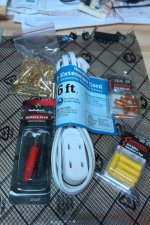
But for the cables we're making, I prefer to fill the crimp with melted solder instead to ensure high current capability and good strength. I never crimp and solder without applying shrink wrap afterward, to protect the joint and prevent too much flexing of the wire right past the solder joint. You can use the paint-on rubber insulation (like is used to coat tool handles but you would have to wait for it to cure, taking a long time) or you can use that wrap-on tape that bonds to itself. I stock heat shrink for this in proper sizes to match the joint and the cable. Soldering irons, solder, heat shrink and the third hand tool are available for very low cost at a Harbor Freight tool store. (no connection, I'm just a customer). If you do go to Harbor Freight to get these items, buy a higher-wattage soldering iron or pistol, something 50 watts or better. I used a 100/140W soldering "gun" for this work and had no trouble at all - my tool of choice for soldering cables and connectors.

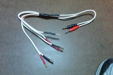
Very Important: Look carefully at the ends of the cable. This cable is polarized throughout, but you have to make it that way. The insulation on one wire is smooth, and on the other is ribbed. I made the ribbed side positive and the smooth side negative. The first thing I did to establish polarity was to solder the banana plugs on - red to ribbed and black to smooth. Then I soldered the positive banana plug to the ribbed side and covered those joints with red heat shrink. I soldered the negative 4mm bullet "jack" to the negative side and covered that in black heat shrink. You cannot let these plugs touch each other when hooking things up. When I use it, I'll plug all the positive plugs into the batteries first, then the negative plugs, then carefully plug the two banana plugs into the already-powered-on charger.
 
Glad to see all of this coming along, and in the easy-to-understand style you're going for.
 
Yeah, that's such a detailed reply,thank you so much, this is a godsend thread.
 
Here's the previously-illustrated charging harness in action. The little 'ol 16 gauge "zip cord" works a treat for charging up to the capacity of this system. (6A/150W available from the power supply, so this is the best current flow I can provide to the balance charger, even though it can provide up to 10A/250W if available.) Look carefully at how the cable is plugged in to match the colors - red to red and black to black. I didn't have to "think" when I did it, I just matched the colors - I did the thinking when I made the cable polarized.

The order was: first all the negative lines to the batteries then the balancing connectors, then powered up the charger and finally plugged in the positive and negative banana plugs to the charger. Nothing in this setup got warm - not the cables, balancing wires, charger or LiPo bricks. I watched the charge process as I sat nearby working, but I did not perceive any danger from the process - the charger worked properly to manage the current flow, balance-charge the bricks and taper to a stop when the bricks reached the terminal voltage configured in the charger. I am completely satisfied with the (overall) 6A charge rate - 2 hours to get the packs to capacity is A-OK by me. (Disclosure: These packs arrive with charge, so this was not from a discharged state - I expect it to take longer after they are used the first time.)

View attachment 2
In the photo above, you are looking at about $140 in LiPo (Hobby King), $8 charging harness, $12 balancing harness, $80 balancing charger and the 150W P/S could be had for $50 or so. If you bought everything, you're looking at just under $300 for this material. I'm not counting my own labor or time here. I've got about 20-25 hours in time researching and ordering the batteries and charger, researching and building the parallel charging harness.


Below is the display of the balancing charger at the beginning of the charge cycle. At this low rate, there's nothing you need to do except keep an eye on the batteries as they charge. It took about 1.5 hours to fully charge all three bricks at the 6A starting rate.

6A charge rate.jpg

Here's the display when the charger finished at the end of the 2 hours. (side note: the astute observer will see this was not enough Wh to charge three bricks - one brick had more charge than the others as I'd played with it already, so I removed it and resumed charging the other two. Cumulative time was about 2 hrs.)

done.jpg

Notice how these voltages fall within the ranges prescribed by the experienced members of this forum: about 3.8v/cell at the start of charging and 4.3v/cell at the end of the charge - you can read that right off the display in the upper right hand corner. Wow....if I'd only had a charger like this for my first electric bike build 35 years ago I'd have gotten far better life out of those lead-acid cells!

Next I'll demonstrate how to make a serial discharge harness for use on the bike and actually fabricating a "battery" from these three Turnigy bricks, connecting the three bricks up to the controller to get an "18S1P" LiPo configuration.
 
Now comes the time to make a series "discharge" harness in order to connect the 3 parallel-charged LiPo bricks to the motor controller. This wiring harness must connect each LiPo brick in series. That gives you 6S + 6S + 6S = 18S. That's over 70 volts "hot off the charger" . I'm going with high voltage because the motor wheel I'm using is a 9c 2810, a slow winding motor that will spin faster with high voltage.

The harness needed to connect the three cells in series is not one-piece like the charging harness. That's because in the first instance, each brick connects directly to the charging port of the charger in parallel, so wiring goes from every brick, merging + and - separately into one conductor for connection to the charger.

In a series harness, it's one cell to one cell to one cell, connecting the + and - of each cell together. Then you use the outside + and - connections to go to the Anderson Powerpole, which then connects to the controller.

We start the harness by soldering powerpole conductors to a 1 foot length of black and a 1 foot length of red 12 Gauge wiring. This is the PVC-covered wiring you can buy for 38 cents/foot at Lowe's Hardware:

30A Anderson Conductors.jpg

Then you snap on the Anderson shells. Match red-to-red and black-to-black. The shells go over the conductors only one way - look closely and you'll be able to see the orientation by comparing the above and below photos - the wires were not moved in the alligator clips, I simply pushed the shells on in the proper orientation.

Anderson Shells.jpg

After the powerpoles, then solder on the 4mm bullets: banana plug to red, bullet receptacle to black. Then make jumpers to connect +/- of each battery together. The color of the jumper doesn't matter, but I snipped off red and black just to conserve wire and matched the color with heat shrink. Each jumper gets a plug and a socket. Here's the completed discharge harness:

Completed Discharge Harnes.jpg

Here's the 18S series harness finished and ready to go, connected to the 6S LiPo bricks. There's over 70 volts at the Anderson connector for use by the controller!

18S_harness.jpg
 
Here's the discharge harness, three LiPo bricks in a simple cardboard box:

making a temporary test battery.jpg

And here's the test battery connected to the controller:

test battery hooked up.jpg
 
CA powers up and reads voltage by default. Both the charging and discharge harnesses have done their job:
 
What's been demonstrated in this thread has been balance charging. Balance charging allows you to precisely control the amount of charge given to each individual cell in a 6S LiPo pack. Balance charging is appropriate for first time pack charging and for occasional use to bring the cells back into balance. The disadvantage to balance charging is that you have to disconnect your pack and charge the cells in parallel, at low voltage. The advantage to bulk charging is that the bulk charger is designed and built to supply the full rated pack voltage and taper off when the pack reaches that voltage.

Normal, healthy cells typically stay in balance and only need to be balance charged every once in awhile. For routine charging you can use a "Bulk Charger", where you attach a battery charger to the final output of the battery pack (the anderson powerpoles) and feed the charger's voltage to the battery. This is necessary if you are going to (for example) commute to work on your ebike and need to charge up the battery at work so you can depart for home with a full charge.

I recently ordered this charger from BMSBATTERY.COM:
http://www.bmsbattery.com/alloy-shell/27-alloy-shell-600w-lifepo4li-ionlead-acid-battery-ebike-charger.html

I'll document how long it takes for the charger to arrive and how well it works when it gets here.
 
built my charging harness today exactly like yours...my soldering looks like someone puked on the wires but works great at .07 ohms lol notice the wire marking for polarization. dont be a nub and cross stuff. camera sux for close ups.

solder001.jpg
 
Kinni420 said:
built my charging harness today exactly like yours...my soldering looks like someone puked on the wires but works great at .07 ohms lol notice the wire marking for polarization. dont be a nub and cross stuff. camera sux for close ups.

Kinni - ROCK and ROLL man! Just make sure it's electrically and physically a good quality connection. Thread the heat shrink down over the remaining connection to be made and give it a go. Post a pic when you are done, or when you use it to charge - if it works, then it's plenty awesome enough! :D
 
Back
Top