Battery pack on Panasonic NCR18650B cell

Gab said:
Hi Agniusm

So its 50% lighter then a123, are you talking the pouch cells or a123 26650 cells ?

Also how much smaller is the volume comparing them ?is it same or smaller volume battery box for same capacity?

I was comparing to pouch cells as they are the lightest in A123 range. I will get a snap side by side with 2 6s a123 to give you an idea regarding volumetric, but I'd say 30% smaller 17ah compared to 20ah.
 
Here are comparison between 12S A123 20AH and 10S Panasonic NCR16850B 17Ah:
20130507_152541

20130507_152523

20130507_152518

A123 size - 223x160x92mm - 3262cm^3
NCR18650B - 240x135x35 - 1134cm^3
60% smaller.
 
really nice/well built/effective layout, you did good on this one too.

did you decide to go with this BMS because it was designed to 10S?

will you do something to hack the shunt to see if you can raise the output current limits?

i am gonna buy some of the 15S D126 to build up some 15S hobbyking packs and was already thinking of how to hack the shunt by soldering another layer of shunt resistors on top of those to double the output power. if the mosfets won't handle it, i will upgrade them too.

if you connect those two sections in series, i would recommend that you make the connection between the two packs a soldered connection so it cannot be physically separated by accident. when the connection goes open while the BMS is connected, then the channel above the break, which would be #6 for you, will burn out the shunt transistor and it will then drain down that cell.

i like the BMS choice though because it is using a digital processor for the controls so it should be much more reliable and the gate voltages on the mosfets would be full voltage so the mosfets won't have issues with partial turn on associated with some other designs.

i may end up with some extra JST-XH connectors if you need them to keep the ability to balance charge it with the 168 or icharger. maybe there is someone close by you too who is scrappping a 5-6S turnigy and they could cut the leads off for you too.
 
dnmun said:
really nice/well built/effective layout, you did good on this one too.

did you decide to go with this BMS because it was designed to 10S?

will you do something to hack the shunt to see if you can raise the output current limits?

i am gonna buy some of the 15S D126 to build up some 15S hobbyking packs and was already thinking of how to hack the shunt by soldering another layer of shunt resistors on top of those to double the output power. if the mosfets won't handle it, i will upgrade them too.

if you connect those two sections in series, i would recommend that you make the connection between the two packs a soldered connection so it cannot be physically separated by accident. when the connection goes open while the BMS is connected, then the channel above the break, which would be #6 for you, will burn out the shunt transistor and it will then drain down that cell.

i like the BMS choice though because it is using a digital processor for the controls so it should be much more reliable and the gate voltages on the mosfets would be full voltage so the mosfets won't have issues with partial turn on associated with some other designs.

i may end up with some extra JST-XH connectors if you need them to keep the ability to balance charge it with the 168 or icharger. maybe there is someone close by you too who is scrappping a 5-6S turnigy and they could cut the leads off for you too.

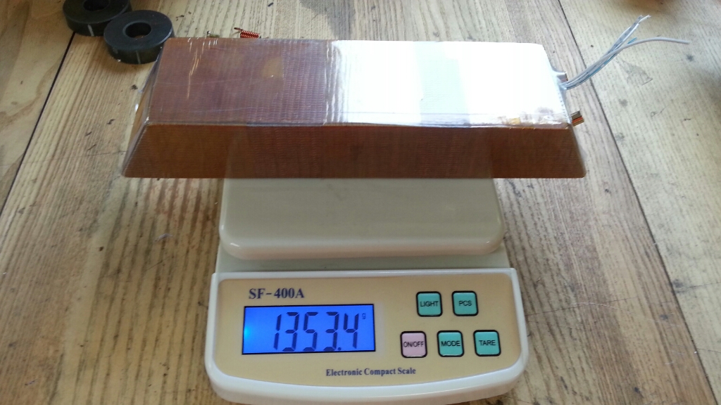
Thanks. The pack is not finished yet. i am thinking of using some fiber reinforced board to put on sides, bottom and top then heatshrinking in a tube.
There was nothing in particular about that BMS. It was 15A constant, small, 10S, that's all i needed
i need to keep them separate as my scooter design requires it to be that way for wire routing. Im not intending plugging it off at all as there is on board charger.
I probably wont increase power as these panasonic cells ar 1C at best and i dont want to push them too hard, after all this will be run about scooter for someone.
I tried it few days ago and 350W 12" hub is nippy, so i am good with that.
For the JST, i have few pigtails made with them, with connectors i use on my A123 kits, they are bigger and has clips, secure.

All in all i am not that good in electronics so swapping something like fets would be job and a half for me :)
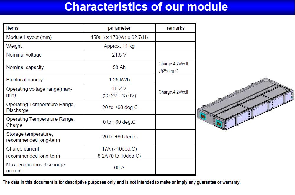
The cycle life is a draw back for me on these cells. otherwise, say in automobile situation they would be great - 270V 100AH pack would weigh 120kg + assembly. Wicked
 
So i got everything hooked up to test BMS. I have requested HVC to be 4.15V but the charger did not cut out till 4.21V. It looked though as it was balancing the pack but again not to the specified voltage.
i charged the pack to 41V and took it for a ride. It was 500m, 100m small slope, started smelling burning electronics, and it was fet on the far right. BMS continued to work, fets were very hot to touch. No current limiting, but again, controller shoud do that at 350W?
20130514_144637

20130514_144631
 
how many amps did it take to smoke that mosfet? they use a nominal 5A/mosfet on their designs it seems so if it cannot handle 40A that is disturbing. can you measure the gate voltage to see if the mosfets are fully turned on?
 
OK, got it all tested. Dont know about checking the gate if its fully open but from negative to left leg returns 9V with or without load. There are 8 mosfets and 4 on the same side as damaged one do not work returning 0V. My assumption is that 20A (4x5A a mosfet) is top limit.
I have attached the brake and was simulating load to check draw, and max it was sucking was 24A.
I suppose this was what caused it to burn out.
i have a vid, will add it when its uploaded...
i think i will order a bigger one from Henry, the 35A one HCX-D100: http://bestechpower.com/37v10spcmbmspcbforli-ionli-polymerbatterypack/PCM-D100.html
2012820155851588.jpg

The balancing function did work properly as it balanced the pack within .00.
 
the 0V means that the mosfets are turned off. the one that burned up is next to the shunt so i am thinking there is one group for charging and one group for discharging. if i could see the underside to follow the traces we could tell more.

ask henry if he will send you some replacement mosfets from their production line with the new BMS, and solder a new one back in there. 9V gate voltage is good so it should be possible to upgrade the mosfets to higher current hexfet type IR parts if you cannot get some replacements.

i am also in communication with him and if he delays about supplying parts i will ask him also. also he is sending me the D131 lipo balancing board after all too so we will have one for educational, demonstration purposes.
 
dnmun said:
the 0V means that the mosfets are turned off. the one that burned up is next to the shunt so i am thinking there is one group for charging and one group for discharging. if i could see the underside to follow the traces we could tell more.

ask henry if he will send you some replacement mosfets from their production line with the new BMS, and solder a new one back in there. 9V gate voltage is good so it should be possible to upgrade the mosfets to higher current hexfet type IR parts if you cannot get some replacements.

i am also in communication with him and if he delays about supplying parts i will ask him also. also he is sending me the D131 lipo balancing board after all too so we will have one for educational, demonstration purposes.

I have the underside photo on page 3. I dont know about charging set. the one that burned was while riding so it must be discharge set but it is still working with the other set which should be for charging?! i cant see logic in that.
here is that vid:

[youtube]Wk5LH_uTZDs[/youtube]

Do you know what higher rated mosfets i could get?
 
there is a reason that the mosfets are turned off. i suspect it sees a LVC signal on one of the sense wires so you may have a bad connection which is provoking the LVC to shut down the mosfets. so check that to see if you can find a low reading on the BMS sense wire plug traces.

i am surprised it did not turn off both sets of mosfets though.
 
dnmun said:
there is a reason that the mosfets are turned off. i suspect it sees a LVC signal on one of the sense wires so you may have a bad connection which is provoking the LVC to shut down the mosfets. so check that to see if you can find a low reading on the BMS sense wire plug traces.

i am surprised it did not turn off both sets of mosfets though.

at bms plug all cells read 4.03V. No variation there
 
I think it's better to just rely on the BMS to balance the pack, and then connect the controller directly to the battery

and then rely on the controller for low voltage disconnect


ok... there's a chance you could have cells at different voltages and run some lower than others... but when the bms is balancing with every charge, the cells should be pretty close :)
 
I hope the 15a operating current is the total amount of battery amps. Each of my packs are about 15a, I bought two of them linked below. Unfortunately it has only a single jst plug so I will have to use both bms and pcm.

http://www.ebay.com/itm/321108391165?ssPageName=STRK:MEWNX:IT&_trksid=p3984.m1439.l2649
 
circuit said:
Toby82 said:
So should we expect commercially available packs with high numbers of 18650 cells configured in both parallel/series (AllCell ect.) to use cells with PTC's fitted?
Tesla does it this way.
pic

pic

pic

pic


But for ebike packs... Doubt it.


Where did you find those pictures? I have been curious how their packs are built.
 
circuit said:
Toby82 said:
So should we expect commercially available packs with high numbers of 18650 cells configured in both parallel/series (AllCell ect.) to use cells with PTC's fitted?
Tesla does it this way.
But for ebike packs... Doubt it.

Have you seen these Panasonic built packs, 21 V and 58Ahr, 60A discharge, using 120 18650 cells
?? possibly reconfigurable to 42v, 29Ahr ??
from here..
http://www.embedded-world.eu/fileadmin/user_upload/pdf/batterie2011/Sonnemann_Panasonic.pdf
z3c2.png


6bt0.png
 
It looks like you got the BMS to work, Agnius
otherDoc
 
Well, i bought another one with higher current. I have damaged the smaller one by desoldering damaged FETs. It could be used thou with discharge bypass i think.
 
Back
Top