Battery Repair Question - Mystery Wire

mlt34

100 kW
Joined
Jan 19, 2011
Messages
1,245
Location
Boston
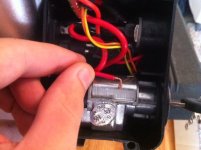
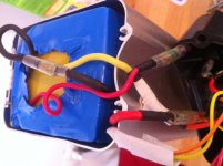
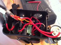
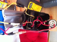
Someone brought me this 36V aluminum case "silverfish" style battery, stating "it was working, then suddenly stopped". He opened it, and as much as I can gather from his explanation, he found a wire coming from the charge fuse to be disconnected, but he wasn't sure where to reconnect it. After looking it over, even I am a bit confused. There are no empty connectors and the wire didn't have any solder on it, so it appears it was in another crimped connector.

There are four wires coming out of the battery. The two red wires are positive power. The thick red wire goes through the keyswitch, then to the discharge fuse, then back to the small red wire. It appears the large red wire comes from the discharge connector at the bottom, though I haven't opened the bottom yet.

The yellow large wire (which turns into an orange large wire) goes to one pin of the charge connector. The other charge connector pin goes to the charge fuse, then from the charge fuse is the mystery red wire. Where does that red wire feed back in? I assume the yellow large wire is the positive charge lead. So then the mystery red wire would be the negative charge lead. It doesn't share the discharge minus, does it?

Oh and a few other bits of info: both fuses are good. No voltage out of discharge or charge connector. Haven't checked the BMS since its still sealed in the shrink and I don't want to open it if i don't have to. The lack of voltage doesn't seem to be a dead battery due to not being able to charge, since it should read something like 35 or 36V and not zero. Also, the LED indicator on top of the battery used to work, but doesn't work now.

Thanks for any help you guys can provide.

Here are pics:
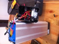
photo 1.JPG
photo 2.JPG
photo 3.JPG
photo 4.JPG
photo 5.JPG
 
alsmith said:
Well, it's not soldered so check for spaces in those crimp connectors

Seriously?

Alright looks like I need to update the original post with something along the lines of "obviously there aren't any clear empty spaces in the crimp connectors or I wouldn't be here."
 
From your pics it does not look like you have taken the bottom of the pack off and withdrawn the cells from the aluminium casing.

If this is the case, my guess is that the other end of that wire belongs down inside the case somewhere...on the BMS board in the opposite end cap.

interesting bit of aftermarket white insulating tape there too
 
The best thing to do is to unwrap the BMS so that you can get to the negative from the cells. Take out the 4 scres from the bottom, then turn the black plastic piece sideways and use it to push the cell-pack up a few inches. With the cell-pack higher you can cut the heat-shrink sleeving in the corners and fold it out and down. The BMS sits on top of the cell-pack. A black wire will come from the cell-pack to the BMS "B-" pad. You can measure all voltages from there. First check between this point and the thick red from the cell pack. This will tell you the pack voltage, which I guess is below 31v, which is why the BMS is shut down (mainly because the charge lead is disconnected, so can't be charged)

Next you can see whether the yellow is positive or negative by measuring fronm the cell thick black. I suspect it's negatie and connected to "C-" pad in which case your spare red lead is the positive charge lead and can join the red thick wire from the cells or anywhere else that's positive.

All switching by the BMS, either charging or discharging is done on the negative wires. It looks to me like your setup follows the schematic below, where the dotted red is connected in your case. There will be a junction pad on the BMA where the positive charge, discharge and cell positive a meet up.

If your BM has switched off because cell voltages have gone too low so that you cant charge. You have to charge the individual cells to get them above the threshold, or you can charge for a bit directly to the cell power wires until the lowest is over about 3.1v. You measure cell voltages at the multipin connector on the BMS.

I might have the B- and P- the wrong way round in this schematic. I need to check, but you'll see on our BMS how it is.

 
thanks d8veh, very detailed. I agree, it looks like the mystery wire should be common with the main positive wire from the cells. The BMS does in fact sit on top, not down by the discharge connector, Neil. And in my defense, the aftermarket tape wasn't mine, it was the guy's handiwork ;)

Oh and I should have mentioned the wire is only a few inches long, so it has to be from somewhere up top, either one of the connectors or straight to the BMS. I believe it should go in with the main red discharge wire, before the key switch.

I'll open up the BMS tomorrow. This was the worst time for my multimeter battery to die and not have any spare 9V's laying around...
 
> The only one I had like that, the BMS was down the bottom.

But just because the wire is short, is no guarantee it came from the top. There could well be a connector that it used to be attached to running down to the bottom of the pack? At least in the one I have had apart, there was enough space for a wire down the side..
 
dnmun said:
very detailed, you agree, but it is wrong.

care to elaborate?
 
NeilP said:
But just because the wire is short, is no guarantee it came from the top.

very true. I'll have to open it up anyways and that will tell for sure.
 
dnmun said:
i already did, i posted it right away when i saw how wrong the connections were on the diagram. did you read what i posted?

woops, yea I read that but then forgot about when I came back and read your second reply. So just to confirm, you are saying P- in fact goes to the negative of the discharge connector while B- is the pack negative?
 
justlooking said:
i have 2 batteries like that one, of you can wait until later i will go and collect them and have a look inside and take pictures for you

Thanks, I'd appreciate it. Specifically where the two wires from the charge connector lead to.
 
ok i looked in mine and it has a different battery, but one wire from the fuse goto the switch and the other goto the BMS which is inside the case.

thats about as much i can help u m8..
 
justlooking said:
i have 2 batteries like that one, of you can wait until later i will go and collect them and have a look inside and take pictures for you
They're not all the same. They have different BMSs and different wiring at the top. In principle, they're similar, but the last ones I opened up had the charge fuse on the negative. There's nothing to stop you wiring it up like the schematic even if it's presently wired differently, although it looks like yours is the same except that you've got the key-switch on the positive power output.

I agree tha the B- and P- are the wrong way round in my schematic above. I must've been sleepy when I did it.
 
Back
Top