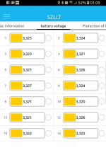
bluetooth BMS?

Hello there!
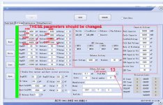
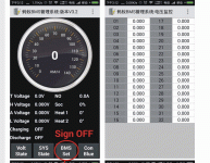
I have put together 13S5P battery with Sanyo/Panasonic NRC18650GA cells with smart bluetooth BMS. The BMS arrived with basic settings already there (see picture). this is fine, but I would like to change this seetings to achive longer cycle life of the pack and to adjuts the BMS to the GA cells. I was thinking to limit useful voltage between 3,1 to 4,1 V? Which parameters should I change? I am not very familiar with this, so I would apperiate your help very much.
THX
View attachment PC tool User instructions.pdf
 
dh68 said:
Hello there!
I have put together 13S5P battery with Sanyo/Panasonic NRC18650GA cells with smart bluetooth BMS. The BMS arrived with basic settings already there (see picture). this is fine, but I would like to change this seetings to achive longer cycle life of the pack and to adjuts the BMS to the GA cells. I was thinking to limit useful voltage between 3,1 to 4,1 V? Which parameters should I change? I am not very familiar with this, so I would apperiate your help very much.
The BMS voltage limits should be set outside the normal operating range. Normally, the charge termination voltage should be determined by the charger, and the low-voltage cutoff should be handled by the controller. If you implement these limits in the BMS, it will shut down charging before actually reaching the desired voltage (due to excess voltage across the battery's internal resistance), and it will disconnect from the controller while there's still capacity in the battery, as the voltage dips when you apply the throttle. It looks like you can partly avoid the second problem in this BMS by adjusting the "Delay" parameters, but it's still not ideal.

Usually it's possible to adjust the termination voltage of even inexpensive chargers. The controller LVC may not be adjustable, so in this case you'd need to have some sort of display so you can keep an eye on the voltage. Read the voltage when the throttle has been at zero for several seconds, to allow the battery time to recover from being loaded.

The function of the BMS is to protect the battery from conditions outside normal operation. For example, a runaway charger that doesn't stop at the termination voltage, an out-of-balance cell group that hits its termination voltage before the rest of the pack, a short circuit, or a load (e.g. lights) that's inadvertently left connected when the bike is in the garage.

All that said, whatever limits you decide on, the CellOVP, CellUVP, PackOVP, and PackUVP are the relevant parameters. If it were me, I'd just rely on the cell-level protection and set the pack levels to something the pack would never reach, but in some cases there may be legitimate reasons to use these.

See also my post about 5 back regarding balancing.
 
Thanks for help. I need some time to think it over. I'll leave it as it is till then.
 
dh68 said:
Thanks for help. I need some time to think it over. I'll leave it as it is till then.

BTW thanks for posting the instructions. It's been hard to find documentation on these.

General question for those who have used these - have you gotten them to work with arbitrary numbers of cell groups? I'm thinking of getting a 20s model for an 18s battery, but I messaged the Aliexpress vendor in the first post and they said this is not possible. However, Inwo says it works if you set the Pack Num parameter. No detail beyond that, though. If you've done this, what parameters did you need to set other than Pack Num? Which balance taps are used?
 
dh68 said:

Thanks, that's helpful. It looks like each model can be configured within a range of cell groups by short-circuiting specific pairs of balance taps. Turns out the one I was looking at is for 20s-30s so 18s wouldn't work, but there's another model listed on the Aliexpress site as 16s but it looks like it can be configured for anything from 16s-20s. I have another message in to them to verify this.
 
I've got this answer after I send my question to the seller/producer (see picture with new settings) although he didn't take my picture with real data as background. Still I don't understand the purpose of those "release" input boxes.
Shouldn't be adjusted settings in the "Capacity Setting" on the right side of the window, too?
How can I calcultate the new capacity of the battery?Settings 3.1V-4.1 V from seller.jpg
Thanks everybody.

The specifications for NCR18650GA are:
- Rated Capacity: 3300mAh (0.67A discharge at 20°C)
- Minimum Capacity: 3350mAh (0.67A discharge at 25°C)
- Typical Capacity: 3450mAh (Reference only)
- Nominal Voltage: 3.6V
- Discharging End Voltage: 2.5V
- Charging Current (Std.): 1475mA (other source 1675A)
- Charging Voltage: 4.20V (+-0.03V)
- Charging Time (Std.): 4.5 hours (other source 4 hours)
- Continuous Discharging Current (Max.): 10A
 
dh68 said:
Still I don't understand the purpose of those "release" input boxes.

I would assume it means that for over-voltage (CellOVF), the protection cuts in if the voltage goes above 4250, and releases again when it drops back below 4100.

For under-voltage (CellUVF) the protection cuts in when the voltage drops below 2700, and releases again when it move back above 3000.

And so on.
 
dh68 said:
How can I calcultate the new capacity of the battery?

thunderheart recently posted some discharge curves for the GA; you should be able to estimate capacity from that. Look at the lowest-current curve and calculate capacity between 4.1 and 3.1 V, then multiply by your parallel count.
 
Thank you for both replies. About the "releases" - it looks logical now.

My TSDZ2 motor is 500 W/48 V, so it would take ~10A at max although there is "15A" label somewhere inside (maybe is it 750W!?). So if I have 13s5p battery, that would be 10to15A/5p=2to3A per cell max. This means, that is better to look somewhere near the red 2A curve in the discharge chart?
In that case I get these estimations:
per cell-___~3A___-____2A___
3,1V ---- 2930mAh - 3050mAh
3,0V ---- 3080mAh - 3140mAh

per 5p-___~3A___-____2A___
3,1V --- 14650mAh - 15250mAh
3,0V --- 15400mAh - 15700mAh

The "logic" about the "Capacity Setting" box in the window is still "black box" :?
 
not to be "that guy". but if you keep below 16S one could just use one of these:
https://www.energusps.com/shop/product/tiny-bms-s516-150a-750a-36
i have used this one for a few packs now and works beautifully. and thanks to orginal parts i know it is good quality unlike the chinese stuff with questionable parts.

personally i am looking into going beyond 16S and looking for a programmable bms but i dont want to rely on the crappy mosfets they have on these bms boards. is there a way to have a external shunt or fitting a relay for OVC protection. otherwise i can only use them as a charging board and need separate fusing adding more cost and parts.
 
You can now order 16-32s Bluetooth bms with mosfet and lcd as options. Up to 300 amps.
I have a few 24s 150amp for testing that I never got around to.
Using a 24s 300 amp on my truck. 22s 110ah.
Chinese of course, but works well.
 
Inwo said:
lto-bms1.gif
I've been using the 10s to 15s 30amp version. Getting the information to reset cell count was like pulling teeth.
There is also a 150a and 300a up to 32s. Optional lcd remote display. All settings can be changed from bt. Even down to LTO 1.5v to 2.75v.
If anyone knows a little bit about this BMS, I would really appreciate some help.
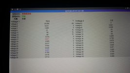
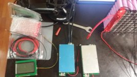
I have 2 of these units, 300a 24s. I bought them for my 20s 10p Samsung 30Q cell pack. The problem is both of these units are showing the same fault. After 5-10 seconds of BMS receiving power, it will start beeping rapidly, and the screen will show the fault in Chinese. I am not able to scroll through the screen anymore after this fault pops up. The seller on aliexpress translated this to charge/discharge MOS closed. They suggested that the MOS tube was defective. I don't know how to check that with a multimeter.

The first unit worked the first few days as the battery sat around at home. I have not been able to discharge through this BMS. I left the bms to balance the pack for a few days while I finished wiring the temp sensors. The bms did a great job and balanced out the cells within .010 of each other. I was very pleased until it stopped working. One morning, I was scrolling through the menu looking over cell voltage, when it suddenly jumps to the fault screen and the bms will not stop beeping.
I realized this issue began after soldering the charge and discharge wires. I figured I burned the Mos tube while soldering?

I bought a second unit from the same seller. I wired it up, and again same issue, the BMS will rapidly beep and the display screen will show the fault.

Supposedly they now have an English version app they promised to send me today. Hopefully a translation can lead me closer to a solution. Does anyone know if I would be able to replace the MOS tube on these units?
 

Attachments

  • 20171213_134413.jpg
    20171213_134413.jpg
    142.9 KB · Views: 5,438
  • 20171213_135212.jpg
    20171213_135212.jpg
    148.4 KB · Views: 5,438
  • 20171130_164302.jpg
    20171130_164302.jpg
    18.8 KB · Views: 5,438
I have that one or just like it.
What seller did you get it from. It might be a knock off, as there is more than 1 seller now.
My app looks different.
 
Inwo said:
I have that one or just like it.
What seller did you get it from. It might be a knock off, as there is more than 1 seller now.
My app looks different.

I saw a few sellers but this was the only seller with a faster shipping option.

I was emailed many different apps, English language app, Russian language app, 2 different Chinese versions, and the MaYi BMS version which I was using in the picture. I never received the app that you show in your picture.
 

Attachments

  • bms.jpg
    bms.jpg
    160.4 KB · Views: 5,411
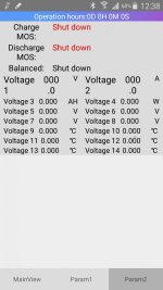
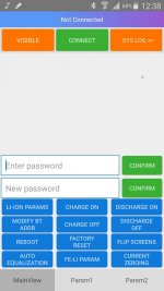
This is the English language app that I received today. It appears to be just a translated English version of the MaYi BMS app.
 

Attachments

  • Screenshot_2017-12-19-12-38-51-1.jpg
    Screenshot_2017-12-19-12-38-51-1.jpg
    74.5 KB · Views: 5,406
  • Screenshot_2017-12-19-12-38-27-1.jpg
    Screenshot_2017-12-19-12-38-27-1.jpg
    91.6 KB · Views: 5,406
Hi all. I am very interested in the Bluetooth bms. I want it for cell group monitoring and another feature is that with my big 14s 34 amp hour battery I can charge to 80% (4.00 volts per cell and by adjusting the balance start to 3.8 volts it will still balance the cells only charging to 80%
My question is do I even need the PC programmer? I ask because bms battery wants 99 bucks for the programmer when it comes with the bms if I buy it from China (Senchan?) Are any of these parameters adjustable via the Bluetooth phone app? It looks like the it can because there is a submit button on the photos of the Bluetooth app page where parameters are. Help lol
 
mattjrogers said:
I have one of these BMS units. Just installed it a week ago and working through its functionality.

I alway hate when a board has conflicting markings - such as a separate place to solder P- and C-, but they tell you to put both wires on the C- tab. Why?

Does anyone know if the P- port works? I'd like to use this for a lifepo4 pack for an offgrid application and want separate load disconnect vs charge disconnect. If the P- for loads doesn't work, then this won't work for me.

Thanks!
 
I think I might have blown my BMS up.

I was hooking it up to the pc for the first time, and wanted to test it all before i put shrink wrap over the battery. Anyway the metal USB end touched the positive terminal of the battery. creating a nice spark! I assume this sent 58v and a truck load of amps through the usb/comm port.

I cant connect with the pc, and cant connect with bluetooth.
voltage out of my battery load / discharge leads now is 2.4v (via bms) directly from the battery shows 48v.

Is there anything I can do to revive this bms, or test components? or is it pretty much a basket case --- and bin it.

Pretty annoyed at myself. usually sooo careful.
 
bin it. com port on the controller chip is fried. probably blew the ADC's as well so the voltage readouts are garbage anyway.

shit happens, i blew up about 900 european roupies worth of electronics the past years just by doing stupid for a second. :(
 
has someone found a way to turn the bms on/off with a switch?
i contacted the seller and they told me to use the temperature sensor. unfortunately the question if it will restart automatically once the "temperature cut off condition" is released, is unclear. do you need to connect/reconnect the battery to reset it?
 
Interesting thread, but a bit hard to follow. There appear to be at least 3 different bluetooth capable BMS products being discussed here, and not always a clear reference to which one is being discussed in a given post. Like, which software screenshots go with which BMS?

Could it be valuable to the community to populate something like a google sheet with the various commercial BMS products (bluetooth and otherwise), their technical specs, links and notes to any associated software, and most importantly people's experience with them. I.e. who's actually got one in-hand and has tested it, and what did they find? Do we already have such a thing somewhere? Just an idea but of course a bit difficult to get going and organized.
 
andrew.box said:
Interesting thread, but a bit hard to follow. There appear to be at least 3 different bluetooth capable BMS products being discussed here, and not always a clear reference to which one is being discussed in a given post. Like, which software screenshots go with which BMS?

Could it be valuable to the community to populate something like a google sheet with the various commercial BMS products (bluetooth and otherwise), their technical specs, links and notes to any associated software, and most importantly people's experience with them. I.e. who's actually got one in-hand and has tested it, and what did they find? Do we already have such a thing somewhere? Just an idea but of course a bit difficult to get going and organized.

I agree with you that this thread is a bag for information related to any "bluettoth capable BMS". I own of those myself.
I think that this information can be stored in the (somewhat hidden) ES wiki: https://endless-sphere.com/forums/viewtopic.php?f=32&t=46070

In the spirit of wikis, everybody is the editor, so feel free to add information and encourage others to do it.

What we can do in this thread is try to identify which models and sources of BMS we have around and make additions on the wiki. I think we should call these category "programmable BMS" instead of bluetooth. You know, any BMS that the manufacturer provides a way to program parameters by the end user (not the reseller). Usually these BMS have a serial port, and an optional Bluetooth adapter or USB2serial is attached.

I like the work of this guy https://github.com/simat/BatteryMonitor/wiki/Generic-Chinese-Bluetooth-BMS-unit-as-data-input
Using that information I propose calling those BMS (like mine), the "JBDTools BMS". I mean, calling by the canonical name of the most complete tool used to program it.
 
izeman said:
has someone found a way to turn the bms on/off with a switch?
i contacted the seller and they told me to use the temperature sensor. unfortunately the question if it will restart automatically once the "temperature cut off condition" is released, is unclear. do you need to connect/reconnect the battery to reset it?

i have a new a 14s5p pack of 30Q cells made.
if you dont use it...you will lose ~ 0,1v in 14 days
thats alot and you have to be carefull if you give this battery to friends or customers who arent that fit about batterys/cells and stuff like that.

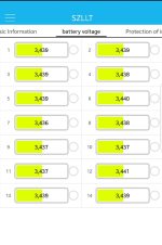
pic 1 is from 09.01.18
pic 2 is from 25.01.18

battery never attached to a controller.
 

Attachments

  • 2018-02-01_03h24_31.png
    2018-02-01_03h24_31.png
    40.5 KB · Views: 4,953
  • 2018-02-01_03h24_44.png
    2018-02-01_03h24_44.png
    40.3 KB · Views: 4,953
Back
Top