Hello ES community, I've been lurking and reading for several months now so thank you for participating in these valuable and interesting forums. I have invested $2,000 in building my own E-Bike only to have the project come to a screeching halt as I tried to charge the battery for the first time. Now I am in need of some technical advice, and I wan't this to be as clear and detailed as possible so I am going to explain my build from the ground up. Skip to the question mark symbol if you don't care to read the background.
I purchased 115 Sanyo-UR18650NSX cells to build two 14s4p 52V battery packs. I tested all of the voltages on the cells to be sure they were good, and they were all reading 3.5 +/- 0.02 Volts. I used nickel strips to connect them together, which I soldered on using a high wattage iron and took painstaking care to touch the batteries for no more than 3 seconds at a time to minimize thermal damage (I didn't have a spot welder). I laser cut the end-cap for the battery so as to include main positive and negative terminal connectors as well as a mini D-sub 15 pin connector (VGA) to access the series element voltages with the BMS. The images below show one of the batteries and the aforementioned end-cap.
https://endless-sphere.com/forums/download/file.php?mode=view&id=212692
https://cdn.shopify.com/s/files/1/0...ur18650nsx_spec_sheet.pdf?2358184305725242569
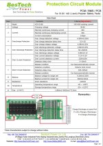
I ordered a custom BMS from BesTech which is, as far as I can tell, properly sized and rated for the batteries I am using. As a note, I had planned on having one BMS and two batteries which I could swap out. This is the reason I added the mini D-sub 15 pin connection and made a custom cable to bridge the battery to the BMS. As far as I can tell this is going to work. If you are building a 52V battery pack and you like the idea of using the VGA port to run your cables through, DO NOT use a standard VGA cable. With most if not all VGA cables for PC monitors, you will cause a direct short between pins within the cable. Anyhow, the datasheet for the BMS is shown below so you can correct me if I'm wrong. At this point I should tell you I purchased a 2014 Trek Mamba, a 1500W 48V conversion kit from Hallomotor, and a Cycle Satiator charging system. Yes I am aware my battery is 52V and my kit is 48V. I've read about over-volting and wanted the ability to do so, but I mainly decided to make the 52V battery so that I could short-charge and extend the lifetime of the pack.
https://endless-sphere.com/forums/download/file.php?mode=view&id=212696
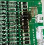
 I wired the battery up very carefully, shrink wrapping every pin connection on the mini D-sub, spacing out contact points, using an organized wiring layout so as not to cross wires...the whole nine yards. I wired up the BMS exactly as shown in the attached datasheet and then I started plugging in connectors. First, I plugged the battery main negative into the BMS battery negative side. Then I connected the mini D-sub cable to the BMS, effectively wiring the BMS to the tops of every series element in the pack. However, before I could plug in the main battery pack positive cable, I smelled smoke and saw the fire coming from the BMS. I immediately unplugged it, but it is fried. Fortunately the minimum order quantity for the custom board was 2, so I have a spare. I would really appreciate any speculation as to the reason for this failure before I attempt to connect my ONLY other board. Here is a photograph of the damage. As far as I can tell, a capacitor was the link that went first, and for some reason it looks like it was the one on series element B10.
https://endless-sphere.com/forums/download/file.php?mode=view&id=212697
I purchased 115 Sanyo-UR18650NSX cells to build two 14s4p 52V battery packs. I tested all of the voltages on the cells to be sure they were good, and they were all reading 3.5 +/- 0.02 Volts. I used nickel strips to connect them together, which I soldered on using a high wattage iron and took painstaking care to touch the batteries for no more than 3 seconds at a time to minimize thermal damage (I didn't have a spot welder). I laser cut the end-cap for the battery so as to include main positive and negative terminal connectors as well as a mini D-sub 15 pin connector (VGA) to access the series element voltages with the BMS. The images below show one of the batteries and the aforementioned end-cap.
https://endless-sphere.com/forums/download/file.php?mode=view&id=212692
https://cdn.shopify.com/s/files/1/0...ur18650nsx_spec_sheet.pdf?2358184305725242569
I ordered a custom BMS from BesTech which is, as far as I can tell, properly sized and rated for the batteries I am using. As a note, I had planned on having one BMS and two batteries which I could swap out. This is the reason I added the mini D-sub 15 pin connection and made a custom cable to bridge the battery to the BMS. As far as I can tell this is going to work. If you are building a 52V battery pack and you like the idea of using the VGA port to run your cables through, DO NOT use a standard VGA cable. With most if not all VGA cables for PC monitors, you will cause a direct short between pins within the cable. Anyhow, the datasheet for the BMS is shown below so you can correct me if I'm wrong. At this point I should tell you I purchased a 2014 Trek Mamba, a 1500W 48V conversion kit from Hallomotor, and a Cycle Satiator charging system. Yes I am aware my battery is 52V and my kit is 48V. I've read about over-volting and wanted the ability to do so, but I mainly decided to make the 52V battery so that I could short-charge and extend the lifetime of the pack.
https://endless-sphere.com/forums/download/file.php?mode=view&id=212696
https://endless-sphere.com/forums/download/file.php?mode=view&id=212697