< < < Boost Control > > >

safe said:
You are probably right. When it came to controller losses I just plugged in the published value (usually 95%) and so I take 5% of the total input current and arrive at an estimate. It's a complicated matter to model correctly and since the value is small I figure this estimate is "good enough".

I wanted to avoid hassling with formulas like:

583a28bec1230c257fd5c7284a25faa2.png


a56ebcae6a918a4b04e2e4e6a1db390c.png


d4974731c1b1faa9c14284c3d2b3c7a9.png


:?: Can you blame me for not wanting to go any further?

Dont be angry, but i must correct you again.
For the sake of my poor language i can't explain you better.

So what is my point ?
I don't blame you you didn't use detail formulas.
I blame you for quite different mistake.

Simple duty formula is D=Vo/Vi as Vo >> Vswitch or V_L
you can also skip Psw at f_sw is low so T is relatively huge to t_rise or t_fall, so Psw=~0
For the same reason (low f_sw ) you can skip P_body diode.
But you should keep in mind that controller's current loss is proportional to actual Vswitch(Iswitch)*Iswitch*D not to the average Vswitch(Iswitch_av)*Iswitch_av.
Actual controller current is the corrent at the motor's side. Average is at the batt's side.
As Iswitch*D = Iswitch_av the difference and your mistake is at Vswitch.
The Iswitch av = controller's I_limit and is constant. Vswitch(Iswitch) = fet's r_DS * Iswitch.
r_DS is relatively constant (in fact it rising as temperature raising but we can skip that detail now as we can assume we have ideal cooling so fet's temperature is constant)
So now you see the controller loss i proportional to the motor current not the battery current.
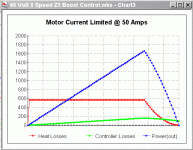
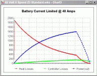
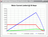
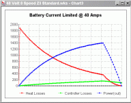
So green line start not at the zero point as blue line(Pout) - the switch loss is greatest at the begining line at the chart. So shortly after green line (falling) crosing the blue line (rising).
The green line should be similar to the red one.
The difference is the green line falling more linearly, red one falling like parabola.

So the second mistake is at the end of the chart.
Green line never crossing the red one. After D reach 100% both green and red lines start to falling sharply but they cant crossing each other.

You could say those are minor mistakes but it is very important if contoller's cooling is bad and controller fail at low P_out and high torque (where the chart begin).

I like yours charts and simulations but i have to correct you if i see you do such critical mistake.
If i didn't correct you - others could will think the everything is ok if they cant check your charts.

Regards
 
Ep:

So you're saying that controllers aren't 95% effecient all the time, and that they have different effiency levels at different speeds. I don't understand all the calculations, but could you tell me the conditions where controllers are most effecient? Least effecient? Is a 24v system's controller going to be more effecient than a 48v controller?

Please estimate the following:

24v controller at low speed = ?%
24v controller at high speed = ?%
48v controller at low speed = ?%
48v controller at high speed = ?%

Thanks for your great input!
 
Beagle123 said:
Ep:

So you're saying that controllers aren't 95% effecient all the time, and that they have different effiency levels at different speeds. I don't understand all the calculations, but could you tell me the conditions where controllers are most effecient? Least effecient? Is a 24v system's controller going to be more effecient than a 48v controller?

Controller efficiency is a minor issue for the system (not important as controller loss is usual far less than motor's heat loss).
But when you want make reliable controller with reliable and capable cooling system you need to know it's max. losses at the worst conditions.
So efficiency is not important. No matter how efficiency is ( how much power motor get ) you need to know controller loss.

Beagle123 said:
Please estimate the following:

24v controller at low speed = ?%
24v controller at high speed = ?%
48v controller at low speed = ?%
48v controller at high speed = ?%

It is a wrong question. Controller's efficiency strongly depends on motor current. So you get quite different efficiency at low speed uphill and at low speed at flat.
The same story is for the high speed - at flat you need high torque (for the sake of air drag)but at downhill yors motor can work at low torque and low current or even you can switch them off.

Controller loss is greater at lower Duty at the same average current. So you can get much higer loss at low Duty (10% for example) than at (90% or 100%WOT) if you push the load to the limit.

Regards
 
Since resistance loss in both the controller and motor are a function of current squared, for the same power level, a 48v system will be more efficient, since it only needs half the current.

There are other losses, but resistance is the main one.

You could use an on/off switch instead of a throttle. I've seen some scooters with this (the old BladeZ). You can have it ramp up at a controlled rate to prevent slamming the drive train.
 
All I was doing is taking the final "Power(Out)" value and multiplying it by the rated controller efficiency. So if the "Power(Out)" is 100 watts at a particular rpm then I assumed 5 watts were lost. I'm sure a more accurate formula could be devised, but the idea was to just take a "sliver" out of the power output so as to approximate the loss.

I could do a lot of extensive work to get the exact formulas in place, but there would be so many variables that you would have to guess at anyway that in the end I doubt that you would get much closer.

:arrow: 5% is a small thing to worry about when the heat losses can be so huge in comparision.

But back to the bigger question:


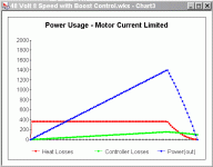
Controller Motor Current Limiting Reduces Heating Substantially :!:
 

Attachments

  • Power Usage - Motor Current Limited 2.gif
    Power Usage - Motor Current Limited 2.gif
    11.1 KB · Views: 3,000
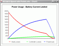
  • Power Usage - Battery Current Limited 2.gif
    Power Usage - Battery Current Limited 2.gif
    12.6 KB · Views: 3,000
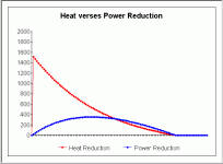
This chart takes the results of the "Motor Current Limiting Controller" and compares it to the standard "Battery Current Limiting Controller" and shows how you get a reduction in torque and heat at low rpm. (high rpms are unchanged)

The torque curve is multiplied by 100 to get scaling to match.

:arrow: This is the REDUCTION of one type to the other... so it SUBTRACTS the values of the previous charts.
 

Attachments

  • Power Usage - Reduction of Torque and Heat.gif
    Power Usage - Reduction of Torque and Heat.gif
    6.7 KB · Views: 2,995
:arrow: This chart is probably easier to understand.

This is the reduction in heat alongside the reduction in power that the restriction causes. You lose power "down low", but you get far less heat and you sacrifice nothing in the "top end".
 

Attachments

  • Power Usage - Reduction of Power and Heat.gif
    Power Usage - Reduction of Power and Heat.gif
    6.8 KB · Views: 2,995
Fechter

At some point this circuit will need to be built for my project. So far I've just started to build the frame, so there's a lot of welding and grinding to go. (a month or more to go)

"Motor Current Limiting" as an idea has increased the value of this circuit in my mind a great deal. This seems to be the "Holy Grail" of geared electric bike control.

Anyway...

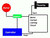
:arrow: The basics seem very simple:

1. Hall Effects Sensor on the motor side current wire as input.

2. Throttle voltage as an input.

3. Some comparision is done to be sure the motor side current never exceeds the adjusted value, so if the current goes too high, then the throttle must be turned down.

4. The only output is the throttle wire.

5. It's also probably going to be necessary to add a small battery to make the circuit work, but being able to do without one would be fantastic.

I know you've been working on a different system ("Current Based Throttle") so I'm interested in any updates or comments.
 

Attachments

  • circuit design.gif
    circuit design.gif
    6.9 KB · Views: 2,905
My guess is that the next "education" I'm going to have to go through is how a "comparator" works. Seems that the "hip" phrase for these "Operational Amplifiers" is "op-amp".

:arrow: Am I thinking about the right circuit component?

180px-741_op-amp_in_TO-5_metal_can_package_close-up.jpg


And if this is correct then the circuit inputs would look something like:

200px-Op-amp_symbol.svg.png


Am I on the right track or way off?
 
safe said:
All I was doing is taking the final "Power(Out)" value and multiplying it by the rated controller efficiency. So if the "Power(Out)" is 100 watts at a particular rpm then I assumed 5 watts were lost. I'm sure a more accurate formula could be devised, but the idea was to just take a "sliver" out of the power output so as to approximate the loss.
...

At stall point the power out is ZERO so you still think your formula controller_loss=power_out*5% is accurate ??

Do you still think that loss will be zero at motor current pushed to max. ?

Regards
 
eP said:
Do you still think that loss will be zero at motor current pushed to max. ?

Don't worry about it, it's not central to the thread topic. The "big picture" is about "Battery Current Limiting" verses "Motor Current Limiting". The "controller heat issue" is separate and not all that important. (it's a few percentage points) Please do not continue debating the wrong issue.

:arrow: Focus on the central issue of the thread.

It's been really hard to keep this thread on track because I really don't think people are fully understanding the purpose of it. Low end torque is a kind of "evil" that produces heat. It's completely possible to eliminate this problem and with no negative effects in the process. That's the central idea here...


Argh... we're on a new page again... here are the two charts again for reference. Please study them carefully and think, think, think...
 

Attachments

  • Motor Current Limit @ 50 Amps.gif
    Motor Current Limit @ 50 Amps.gif
    13.7 KB · Views: 3,164
  • Battery Current Limited @ 40 Amps.gif
    Battery Current Limited @ 40 Amps.gif
    13.4 KB · Views: 3,164
Did YOU ever stop to think...

Heat is the inevitable byproduct of torque?

Just imagine... application of torque requires an oppositional force (inertia) = resistance = heat.

By reducing the current, you reduce the torque. Less heat, less power.

The real solution is a better motor (not a bigger motor).

:roll:
 
safe said:
eP said:
Do you still think that loss will be zero at motor current pushed to max. ?

Don't worry about it, it's not central to the thread topic. The "big picture" is about "Battery Current Limiting" verses "Motor Current Limiting". The "controller heat issue" is separate and not all that important. (it's a few percentage points) Please do not continue debating the wrong issue.

:arrow: Focus on the central issue of the thread.

It's been really hard to keep this thread on track because I really don't think people are fully understanding the purpose of it. Low end torque is a kind of "evil" that produces heat. It's completely possible to eliminate this problem and with no negative effects in the process. That's the central idea here...
You are wrong my friend.
You cannot eliminate heat by limiting motor torque.
If your motor give you insufficient torque you go to the stall point and your efficiency will go to ZERO.

And you still get the loss at controller. So controller loss generally is not a minor issue. For very efficient motor (very low Rm -winding resistance) motor heat loss and controller heat loss could be comparable !! - you shouldn't forget that case.
So please rethink all again and correct the green line !

safe said:
Argh... we're on a new page again... here are the two charts again for reference. Please study them carefully and think, think, think...

I am still doing that my Dear. :D

Cheers
 
TylerDurden said:
Did YOU ever stop to think...

Heat is the inevitable byproduct of torque?

Just imagine... application of torque requires an oppositional force (inertia) = resistance = heat.

By reducing the current, you reduce the torque. Less heat, less power.

The real solution is a better motor (not a bigger motor).

:roll:

I am looking for people which are able think as good as you TD

Thanks again (I see i'm not alone here :) )
 
You guys are BOTH wrong.

Torque is just one piece of the puzzle. The "other" piece is gearing. By increasing the gear ratio you LOWER the torque at the hub (rear wheel) and by reducing the gear ratio you RAISE the torque at the hub.

Are you "getting it" now? :wink:

Torque is just HALF of the equation. And if you "spin" the motor faster you can get more power because at higher rpms you use less current to spin the motor. At some point you spin so fast that it begins working against itself (Back EMF) and you go "past peak".

Now I understand why you guys have not gone "wow"... you are looking at it from torque alone which if you do that you won't "get it".

Try again... I'm 100% certain of what I'm saying...

The lightbulb is going to turn on pretty soon :idea:

Try to understand what I'm REALLY saying and not what you think I'm saying. There is a "jewel" of knowledge here that most people haven't seen and that's why people are having troubles with it.

"Gearing Changes Torque" (at the rear wheel).
 

Attachments

  • Motor Current Limit @ 50 Amps.gif
    Motor Current Limit @ 50 Amps.gif
    13.7 KB · Views: 3,150
  • Battery Current Limited @ 40 Amps.gif
    Battery Current Limited @ 40 Amps.gif
    13.4 KB · Views: 3,150
David Verses Goliath

Generally it's agreed that a big motor is always better than a small motor. We could go back and review this if you like, but suffice to say this is (within reason) a "truth".

However, big motors can also weigh a lot. Something like an Etek or PMG 132 is a fantastic motor, but they weigh around 20-25 lbs. A small motor that can produce the "legal limit" of 1-2 hp can weigh in the range of 5-15 lbs. So if it's possible to "tweak" the small motor and add gears to it so that it pumps out enough power and is efficient while doing it (no heating problems) then you can argue that you get what you need for a lot less weight.

Imagine a 750 Watt MY1020Z3 being tricked out with 48 Volts, an 8 speed internally geared hub and "Motor Current Limiting" so as to prevent heat from destroying the motor.

:arrow: That's the "big concept" here... how best can you "trick out" a small lightweight motor so as to get performance that you would normally expect from something twice it's weight...
 
Big motors not only weigh more, but will have a higher no-load current. You need to match the size of the motor to the application.

Motor current limiting is easily implemented. With the proper limit, the motor should be fairly bulletproof.

Ideally, I think a limiter with motor temperature feedback would be good. You can run a higher current when it's cold, then the limit starts dropping as the motor temp increases. If you just stay at a lower limit, overheating can be avoided, but it's fun to have extra power when you can get it.
 
:arrow: Fechter, I'm glad you understand what I'm saying.

Would you agree that something like "Boost Control" tied to "Motor Current Limiting" would be about as good as you can get for the person using gears?

I thought it might be nice to be able to simply "turn off" the "Boost Control" circuit and then it would revert to high torque behavior. Doing that might be dangerous, however, because the logic would be that you would "push to the limit" your internally geared hub related stresses since you would have confidence that no "surprise" torque would ever happen.

With gears torque is increased by just lowering the gear ratio... you don't need to "brute force" your way through things all the time...
 
safe said:
You guys are BOTH wrong.

Torque is just one piece of the puzzle. The "other" piece is gearing. By increasing the gear ratio you LOWER the torque at the hub (rear wheel) and by reducing the gear ratio you RAISE the torque at the hub.

Are you "getting it" now? :wink:

Yes my friend. We get it a lot time ago. :wink:
The problem is (when you use one geared motor only) you need high torque both at low and at the high speed. So many gears are not very useful.
We can assume we always using higest ratio gear.
Brushless motor is able to work at wide rpm range, so at the same gear you can get 4mph or 40mph.

safe said:


Torque is just HALF of the equation. And if you "spin" the motor faster you can get more power because at higher rpms you use less current to spin the motor. At some point you spin so fast that it begins working against itself (Back EMF) and you go "past peak".

Now I understand why you guys have not gone "wow"... you are looking at it from torque alone which if you do that you won't "get it".

Try again... I'm 100% certain of what I'm saying...

The lightbulb is going to turn on pretty soon :idea:

Try to understand what I'm REALLY saying and not what you think I'm saying. There is a "jewel" of knowledge here that most people haven't seen and that's why people are having troubles with it.

"Gearing Changes Torque" (at the rear wheel).
[/b][/color][/size]

The second problem is the gearing cost. Gearing could be useful for narrow range rpm cheap brushed motors, but gearing cost is prohibitive at that case.
So lets compare BLDC motor + controller cost versus gearing hub cost.

Regards

ps. Correct the green line - now it is not the controller loss, it is line of mind loss :wink:
 
Torque Multiplication?

Right now I've upgraded to a 1000 Watt Unite motor that produces a peak torque of right around 3.2 Newton Meters at the motor itself. It then goes from 11 teeth to 80 teeth, then after that it goes from 19 teeth to 28 teeth in low gear.

So:

3.2 Nm * 80/11 * 28/19 = 36 Nm at the rear wheel.

Subtract efficiency losses and you get about 34.7 Nm at the rear wheel.

:arrow: The "bottom line" is that with gears a little tiny motor that only produces 3.2 Nm of torque can in real life produce about 10 times that if you gear it down. On my 140 lb bike this much torque is enough to get me up a hill of about 6% slope.

So torque and current are not related at the rear wheel... it's the choices that you make in between that count. (and the "Motor Current Limited" controller decision is ONE of those design choices)
 
eP said:
Brushless motor is able to work at wide rpm range, so at the same gear you can get 4mph or 40mph.

All that the brushless motor adds is a slight increase in overall efficiency, it doesn't change any of the core laws of physics that define the motor.

Gearing is cheap... you can get an internally geared 8 speed for $122 that is very solid. (I found a throw away 3 speed bike yesterday and now I might even use that for some testing)

But I don't want to "divert the thread". We've had threads that debated "Hub Motors verses Geared Bikes" and those were good debates. This thread is NOT about controller heat losses and NOT about other options with bikes.

Let me repeat...

:arrow: This thread is about the very narrowly defined issue of "Battery Current Limited" control verses "Motor Current Limited" control.

So keep focused on the core concept... the question has to be about whether a small motor can be made to do the same work as a much larger and heavier motor. If this technique is used you can get some really good performance without producing much heat... as long as your gears are properly configured.
 
TylerDurden said:
safe said:
3.2 Nm * 80/11 * 28/19 = 36 Nm at the rear wheel.

at what rpm?

:?:

2849 rpm (pretty much peak power which is at 2886 rpm)

But I think you can see that the lower you gear a bike the higher the torque gets. It's limited only by the amount of gear reduction you can achieve. So "torque" is one issue at the motor, but at the rear wheel you have a large amount of freedom to play around with different concepts. By narrowing the powerband you do what every race car / race motorycle has done for years which is to create a "peaky" machine. You can get very good performance with a big motor, but then there's the extra 10 - 15 lbs that is required for such a thing. Even the hub motors I've heard are in the 20+ lbs range... so we're not talking about a trivial weight difference. Think of being able to replace those 10 lbs of extra steel with batteries... or alternatively... think of how much more power you could get if you geared the big motor and pushed it to it's limit.

A "peaky" motor combined with gears "seems" to offer a superior weight situation over the "big motor" concept...
 
TylerDurden said:
rear wheel at what rpm?

That would be:

2849 * 11/80 * 19/28 = 265 rpm

Directly it's RPM * 0.007221696 = 20.57461313 mph

Is there a "larger" question in this somewhere?
 
Back
Top