Brake disconnect

Eric G

1 kW
Joined
Feb 9, 2007
Messages
409
Location
Ontario Canada
Hi
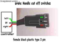
With what I've read about throttles sometimes failing makes me think I should connect up the brake disconnect.The reason it isn't allready done is the wire colours from the brake didn't match up with disconnect wires on the controller.

I need confirmation on how to check the wires coming off the controller with a DVM....(I'm new at all this and it scares me that I'll fry the controller)

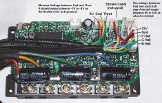
Is this the right way.... Set the DVM to volts....put the common test lead (-black) to the -(black) of the battery....put the red + test lead to one of the 3 wires coming from the controller brake disconnect. Check all the wires,2 of them should have a voltage reading and one should read 0v.

Then hook up the 2 brake lever wires one to the wire with voltage and the other to the 0 volt wire.Then do the same for the other brake lever.

A correction or confirmation would be much appreciated

Eric
 
hi, on the xlyte controller its the yellow and green wires in the brake cable, short them together and you get no throttle. so you can connect either brake lever as a pair in parallel assuming the brake levers make when operated?

Cheers

Knoxie
 
Thanks for the input Knoxie & Ypedal,
I'm still failing at grasping this...I've got 3 wires for the brake disconnect coming out of the controller (clyte) they'e yellow,green and red. On each brake lever there are 3 wires as well white,black and red I believe. The brake levers came with the original ebike. I'm changing the original motor and controller over to a crystalite motor and controller so I'm marrying the old brake levers to the clyte controller brake disconnect. Why and what am I failing to understand.What of the third wire???I'm feeling rather stupid about this.Arrgh!

I need more on this help please...
Eric
 
Brake cut-off, as far as i know, is done by either " Open " or " Closed circuit .

Open circuit - Light OFF - picture 2 wires.. + and - , with a switch, conected to a light bulb. when you flip the switch, you OPEN the circuit.. turning off the light..


Closed circuit - Light ON - you flip the same switch, and you make contact between the 2 wires closing the circuit and turning ON the light.

Your brake levers will " close circuit " , as per Knox, whe the yellow and green wires are conected, the motor will not go.

On the levers themselves, there is usually a magnet on one side, and a metal switch on the other.. when you pull the brake lever, the switch gets too far away from the magnet to stay " Open " and it shuts the controller down. When you release the brake lever, the magnet pulls the switch apart " Opening " the circuit and allowing the controller to work.
 
I'll have to check on that one when I get back to work where my ripped apart controller is. I don't use the brake switches, so I haven't paid any attention to them.

As far as I know, the brake switches are normally open, and close when you apply the brake. This shorts the throttle wiper to ground, stopping the output. The 5v supply for the throttle is short circuit protected and limits at around 100ma.

You could measure the voltage on the 3 wires with power on. Put the meter neg to battery neg. Measure the three wires with the positive lead of the meter. I would expect one wire is grounded (zero), and one goes to the throttle, which would read something if the throttle was applied. I have no clue what the third one would be doing.
 
Eric,

If you can, upload some close-ups of your controller circuitboard; front and back. We might visually determine if the traces are in parallel with the throttle.

You could check them for continuity with the throttle leads using the DVM.


:?:
 
the goofy part, is three wires on the brake levers

:?:

edit: (laptop battery died while posting...) if the disconnect is a simple closure, only two wires are needed at the levers.
 
Thanks Everybody...

This has been driving me nuts but it's starting to get clearer.I've found this image below while Googling brake disconnects and anything that was remotely related to that topic.

Ypedal,you were right with the "three wires,two brake levers"thought.The wire colours in the image don't quite match,so I'll test for a zero volt wire as Fechter said with the DVM then go from there.If that doesn't work I'll post some pics as Tyler said,hope it dosen't come to that as the controller is all retro wired in. (still using the old keyed switch and recharging port)

The three wires on each brake lever,Hmmm I'll set the meter to ohms and check each wire for an open or closed switched state while pulling on the brake lever,who knows one of those wires may lead to nothing.(The original bike maker using whatever covered wire they had on hand and used 3 lead instead of 2).

It's a bummer I won't be able to get to this today as it's Sunday and I'm obligated to do the Family visit thing,you know Parents ,Kids and Grand Kids...Wow time flies.

I'll report back with the results

Thanks alot for all the help,don't know what I'd do if it wasn't for the crew here,soooo much smarts and info...

Eric
 

Attachments

  • brake1small.jpg
    brake1small.jpg
    9.2 KB · Views: 3,213
Hi guy's
I just got a new clyte 72V 35A controller but there is no brake cutoff connector.

So my question is could a connector be placed inline on the throttle connector to place the brake in paralell ?.
If so how do i wire it ?.

fechter said:
As far as I know, the brake switches are normally open, and close when you apply the brake. This shorts the throttle wiper to ground, stopping the output. The 5v supply for the throttle is short circuit protected and limits at around 100ma.
 
One option would be to take out 4 screws and open the end of the controller that has the wires coming out and find the official brake switch connector inside. It's conveniently located on the board right at the end, so it's easy to reach. It has 3 pins, the middle pin is ground, and the brake goes to the pin closest to the end. It would be best to have a mating connector to plug in, but you could pry the plug body off the board and solder directly to the pins.

Another option would be to tie into the throttle wires.

Color codes vary somewhat, but on mine, the red and green throttle wires would be the ones to short.

If you expose the throttle wires and tap into the red and green wires (don't insert the brake switch wires, put them in parallel), then you could go to both brake switches from there.

Either way seems to work fine.
 
Got it all done today and it works....
On my controller the wires work as follows...
1)-Green wire = 4.89 volts
2)-Yellow wire = 0 volts
3)-Red wire = 4.92 volts

The reed switch is a single pole double throw Form "C" type.
Here's a pic to help out on where these wires are in the controller. and a pic I found of the Reed Switch.

Hope this helps you too 29a

Thankyou all

Eric
 

Attachments

  • Open_Controller_Connections.jpg
    Open_Controller_Connections.jpg
    90.8 KB · Views: 3,144
OOPS... Forgot to mention I hooked the yellow wire (controller) to the black wire (reed switch),Green wire (controller) to the white wire (reed switch),for the normally open mode. I only need one Brake cut out.I didn't have the proper wire from the brake to the controller so I use phone extension wire,seems to work well.
 
A tip over switch wouldn't be a bad idea as well, just don't do it the Suzuki way.

http://www.mototuneusa.com/gsxr_tip_over_switch.htm
 
I got a response from justin re clyte ebrake cutoffs seems to contradict
whats above could someone clarify.

Are there controllers made that don"t have the brake connector?,

Exactly. But if you want, there is an ebrake line brought out in the
6-pin DrainBrain connector that you can access.
The ebrake switches are actually open collector hall effect transistors.

does the ebrake short the throttle wiper to ground, stopping the
output ?(If so it should be possible to place a connector on throttle connector to place brake in parallel.)

No, you can actively pull the throttle signal up, but if you have a
high throttle signal and pull it down to ground you will draw up to
40-50 mA from the throttle output and possibly cause damage.


-------------------
So there's access to the ebrakes in the 6 pin DB connector, though I'm not sure how to get at it and make it work !

Anyone know :?:
 
29a said:
does the ebrake short the throttle wiper to ground, stopping the
output ?(If so it should be possible to place a connector on throttle connector to place brake in parallel.)

No, you can actively pull the throttle signal up, but if you have a
high throttle signal and pull it down to ground you will draw up to
40-50 mA from the throttle output and possibly cause damage.


-------------------
So there's access to the ebrakes in the 6 pin DB connector, though I'm not sure how to get at it and make it work !

Anyone know :?:

I doubt it would cause any damage, as I've seen this approach used on many brushed controllers. The 5v supply regulator is short circuit protected. Normally, the throttle would be at zero most of the time when braking anyway.

To really make sure, you could insert a 1k resistor in series with the throttle signal and put the brake switch on the controller side of the resistor. This way when the signal gets pulled down, the 1k resistor limits the current to under 5ma. Since the input impedance of the controller is around 100k, the 1k series resistance does not create a significant drop. Controller input resistance may vary, so to check, disconnect the throttle and measure the resistance between ground and signal pins going into the controller (power off).

I've never seen a DB connector, so you'd have to open up the controller and see where the wires go to the board. The DB isn't going to do anything with the brake signals, so I'm not sure why it would have the brake connections.
 
Heres pics of DB six wires, conections (from 48V 35A crylte)
Black + blue go to same place, power from batt side of shunt
White goes to the other end of the shunt
Green + yellow you can see
Red is conected to something that looks like a cap above chip

Anyone tell me me which of these wires the ebrake connection should go to :?:
 

Attachments

  • DB wires.JPG
    DB wires.JPG
    23.9 KB · Views: 1,996
  • red wire.JPG
    red wire.JPG
    23.4 KB · Views: 1,996
The red wire is the power for the DrainBrain. The capacitor looking thing is a PTC, which is like a self-resetting circuit breaker.

The brake connector on the controller is near where the yellow and green wires are going. The yellow and green wires are actually going in parallel with the overtemp thermostat, which I guess will stop the controller.

Hook your brake to the yellow and green wires. When the switch closes, the controller output will stop.
 
Back
Top