Bubba’s Build 2 Morphing to Build 3

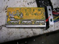
I got the 12 fet controller hooked up and it seems to be working. There are no street lights in my neighborhood, so my test ride was just in front of the house. The first hall/phase combination that seemed to work was only good on the bike stand. It ran smooth all the way through full throttle on the stand, but on the road it would get you going and then stall as more throttle was applied. I found another hall/phase combination that worked on the stand and the road, but I will have to wait until tomorrow to do the real test.

Bubba
 
I am mildly disappointed with my 12 fet controller. Most of the things I am disappointed with have been talked about, but sometimes finding the solution in all the posts can be frustrating.

1. The physical throttle range is small. Most of the throttle movement that affects a change in speed is a small arc in the middle.

2. Acceleration is slow. The maximum continuous amps is about 27 amps. But I have seen peak amps as high as 64 amps according the my Cycle Assist. I ordered the controller with the LVC set to 36 volts and assumed that the battery current would be set to standard 35 amps, but this does not seem to be the case. I will hook my Eagle Tree back up to get a better picture of my current usage.

3. Top Speed is low. No matter how I adjust the hall effects the top speed of the unloaded rear wheel is 64 mph. With the CC the top speed was 77 mph. My buddy has a scope, so I will schedule some time with him to look at the phase outputs to see if there is any modulation.

4. Confusing programming Instructions. This may just be my problem of not having enough hacker in me. I have booked marked the links that discuss programing the controller and after having reading through them still have questions. There is still a lot of re-reading and studying for me to do. Programming the controller is key to resolving some of my issues. My board had 6 holes for the programmer connections, so I brought all six out so that I can program without opening the case. After I did this I found a picture that showed me that I only need the first five wires.

4.1 There might be two versions of Parameter Designer. Just were is the official getting place for the software?
4.2 Does the software read the existing parameter?
4.3 How do you know that your parameters have been accepted by the controller?
4.4 Does a document/thread exist that correctly describes what the parameter do? I seen good starts on this with some being in word or pdf documents and some being buried in threads.
4.5 How do you make the controller accept new parameters? On the newer boards, Methods is saying lift the ground.

A good point is that the traces on my board came already beefed up as you can see in the picture.

Bubba
 

Attachments

  • 12 fet back.jpg
    12 fet back.jpg
    85.4 KB · Views: 2,436
Oops!!!!! I let the neg of the hall effects come in contact with the positive lead of the battery. It happened when I sat down on the couch with the controller beside me. Tomorrow I will see if the controller stills works. The wife is a bit pissed.

I was close to getting the programming to work. The program was trying to transmit, but the controller didn't seem to be responding.

Oh yea. Don't buy a cheep couch from Rooms To Go. Where you sit is leather, but the vinyl on the sides has started to break apart.

Bubba

P1010071.JPG
 
I guess your wife can enjoy the pleasure of your company in the lounge room while you are tinkering and accept the risks that go with it, or she can banish you to the shed. :D
 
Bubba is not having much luck with controllers. When I got this board, I thought that it arrived with beefed up traces as people were saying was need for running more current and I didn't need to do anything. I didn't realize that beefing meant to remove all the solder and wire that came from the factory and add your own. Hopefully the burned trace is my only problem. It looks to be fixable and I will be beefing the board.

Bubba
 

Attachments

  • file.jpg
    file.jpg
    85.4 KB · Views: 2,293
  • P1010082.jpg
    P1010082.jpg
    112.5 KB · Views: 2,276
  • P10100821.jpg
    P10100821.jpg
    22.5 KB · Views: 2,291
I finally got my 18 fet controller hooked up. Had to expand the lower bay for the controller and rewire everything. The cheep bearings that I was using on the jack shaft were replace with some nice high speed ones. The inner race of the new bearings protrudes less, so I need to cut some new spacers and adjust the chain alignment. The controller and hall effects still need to be dialed in. It pulled good up to about 20 mph and then seem to cut out a little.

Bubba
 

Attachments

  • P1010110.JPG
    P1010110.JPG
    113.5 KB · Views: 2,187
  • P1010113.JPG
    P1010113.JPG
    112.8 KB · Views: 2,187
HI Bubba,
The cutting out is most likely that the timing needs a slight tweeking, this is what I found.

edit: If you are still having problems after a tweeking then it could be to do with the length of the hall leads, did you screen them back to the controller ?.
 
gwhy! said:
HI Bubba,
The cutting out is most likely that the timing needs a slight tweeking, this is what I found.

edit: If you are still having problems after a tweeking then it could be to do with the length of the hall leads, did you screen them back to the controller ?.

I did not use shielded cable for the hall effects, but will give it a try if all else fails. The weather is not looking good for the weekend, so I may not get any ride time in for tweaking.

A buddy of my gave me an old dual trace scope. Can you look at a hall effect signal and a motor phase to determine if your timing is correct?

Bubba
 
dontsendbubbamail said:
I did not use shielded cable for the hall effects, but will give it a try if all else fails. The weather is not looking good for the weekend, so I may not get any ride time in for tweaking.

A buddy of my gave me an old dual trace scope. Can you look at a hall effect signal and a motor phase to determine if your timing is correct?

Bubba

Do you have the cutting out happen with the wheel lifted off the ground i.e no load. You can connect one channel to the phase wires and the other channel to the corresponding hall signal and you should be able to see the phase voltage start the same time the hall rising edge starts and the phase voltage stop the same time as the hall signal drops back to 0v . The phase voltage will be pulsed during this time until the throttle is at wot but should have no pulses at full throttle. I found that on the bench the motor would cut out at wot if the timing was slightly out but I found the best way to adjust was to move the position of the halls back a little ( opposite direction to the way the motor spins ) maybe 1 or 2 degrees. I hope this is clear ( i am not the best at explaning things ).
 
Thanks for the info. I didn't notice any issues under no load, but it has been a while since I tried that. If life will stop getting in the way, I plan to set it up on the trainer, hook up the scope and do a little testing.

Bubba
 
I messed around with the hall effect position a bit, but could not get rid of the shuddering while I was going up a hill at full throttle. My scope said I was close on the position. The 18 fet controller was ordered configured as 48V, 60 amps continuous. Peak amps according to my Cycle Assist was around 60 amps and the I could see around 35 amps on the continuous amp display while going up the hill. This was the controller that I was not going to modify, but I was not getting what I wanted out of it. I suspected the controller setting my be my problem.

I programmed the controller to the values in the picture below, the shuddering mostly went away, and my performance expectations are now being met. Going up the hill, I am seeing around 55 amps continuous and 120 amps peak. So I think that the controller is now really set to 57 amps continuous. The controller seemed to stay cool, so I am hoping that I will not melt the solder off the board with these settings. A little tweak of the hall effect positions seem to mostly eliminate the shuddering. More tweaking and testing is needed, but I ran out of sun light.

Bubba
 

Attachments

  • Program 18 fet.jpg
    Program 18 fet.jpg
    52.1 KB · Views: 1,892
It was a beautiful warm day today, so I went for a ride. It was a great ride because it is the first ride in a long time where everything was working. New gearing now has my top speed at 35 mph instead of 50 mph. I am still fearful that the controller might melt the solder off the traces, since I have it set at the max settings. It runs cool, but I still worry, because there is only a small gauge wire beefing up the traces. I am in the process of beefing up the traces of my backup controller with flattened solid 10 gauge wire and will switch it out soon. The power and phase wiring on the Keywin's 18 fets controllers is around 8 gauge with lots of strands, so is very flexible. The down side is that the insulation has a low melting point and just fits through the hole in the end mounting plate with no chafing protection. It turns to mush when you solder it. The rest of my system is 10 gauge, so I may forgo putting 8 gauge back.

Bubba
 
Nice one Bubba,
So did you get rid of the shuddering all together?. Try not to worry to much about the controller as regards melting solder it would have to get extremely hot.
 
I think that the shuddering is mostly resolved. Changing the programming setting and adjusting the hall effect position seems to have gotten rid of the problem. It would have been nice to know which of the programming changes effected the most change, but I took the shotgun approach. I had neglected to ask Keywin to send the config file with the controller. At least now I know exactly what the program settings are. Now I need to hook the scope back up and see if I can see a difference between where I had the hall effects and where they are now.

My goal is to have the hall effects inside the motor. In the future it would be nice to forgo the trial and error method and use the scope to set the position. If that is not possible, maybe set them knowingly a little advanced and then have a adjustable delay on the signal lines.

I feel build 4 coming on. HobbyKing finally got some HXT 80-100 motors in and I have one on order.

Bubba
 
It was a beautiful warm day today. Trees still have some leaves with fall colors. It was a very nice 40 mile ride today. I really like not have to carry water on my back. The new mount for the water bottles works great. It clears the motor assembly by about 1/4".

Bubba
 

Attachments

  • Bottles.jpg
    Bottles.jpg
    95.8 KB · Views: 1,705
dontsendbubbamail said:
My goal is to have the hall effects inside the motor. In the future it would be nice to forgo the trial and error method and use the scope to set the position. If that is not possible, maybe set them knowingly a little advanced and then have a adjustable delay on the signal lines.

Bubba

Hi Babba
I ordered this motor recently
http://www.hobbycity.com/hobbycity/...80-85-B_170Kv_Brushless_Outrunner_(eq:_70-40)

but hobbycity sent a Turnigy C8085-170 it looks very similar to the the motor your using. I tried fitted the halls inside the motor, It do work but be warned the timing is quite away out if you fit the sensors in the slots and draws x3 the idle current, so Im going to revert back to making a hall mount for the outside of my motor that can be adjusted like my other motors. It should not be to difficult to make a electronic adjustable timing interface but I dont think I will bother, I quite like the idea of the halls being easily replaced.
 
gwhy! said:
but hobbycity sent a Turnigy C8085-170 it looks very similar to the the motor your using. I tried fitted the halls inside the motor, It do work but be warned the timing is quite away out if you fit the sensors in the slots and draws x3 the idle current, so Im going to revert back to making a hall mount for the outside of my motor that can be adjusted like my other motors. It should not be to difficult to make a electronic adjustable timing interface but I dont think I will bother, I quite like the idea of the halls being easily replaced.


I have ordered 3 HXT motors and they all came with the Turnigy name on them. The good thing is that you have the newer design that supports the front of the bell. My 80 85 wiring burned up when my Rc controller went bad so if you ever need mechanical parts let me know. Go ahead and order 4 new bearing. 21 mm OD, 5 mm w, 12mm id. I got mine from VXB.com, but don't have the exact part number for you. Thanks for the info on the hall effect placement.

Bubba
 
Thanks Bubba for the offer of spare machanical parts for this motor should I need them ( hopefully I wont :? ) , Yes I will order some better bearings thanks for the info.
 
Update on my Turnigy C8085-170 after fitting internal hall sensors, the problem I am having with the high current draw Turns out its not the timing :!: ( well it is ever so slightly out ) but not enough to cause the extra high idle current. It draws nearly the same current when I use a sensorless controller I have measured the windings and none appear to be short :!: also there is no drag from the bearings so it looks like it may be down to the glue/epoxy that I used to stick the hall sensors in place within the motor. I will have to remove the halls to confirm this. Bubba do you know what the exact idle/no load curret was with your motor before it burnt up :?: . Once I have got to the bottom of this I will post the outcome.

Edit: No is not what I stuck the halls in with :( , looks like it just may be a faulty motor. After 1 min of running full speed on the bench with no load I gets really hot , Initially it started out drawing 10A but after running for 1 min this current dropped to 6A ( wish I had run it up before i started messing around with it :evil: ). It would be intresting to know what the no load current should be for this motor.
 
Paul.............D said:
Hi gwhy

I read another forum been looking for it again but cant find it, they said on that motor it had to be done external as flux interfere's with halls

Paul

Hi Paul thanks for the info but after removing the halls and then running the motor up with a sensorless controller it still is drawing way to much current and still getting hot. I cant work out why this should be , each winding is generating the same voltage and also the same current when the motor is spun up with a drill so I am at a loss as to what is wrong with it.
 
gwhy! said:
Edit: No is not what I stuck the halls in with :( , looks like it just may be a faulty motor. After 1 min of running full speed on the bench with no load I gets really hot , Initially it started out drawing 10A but after running for 1 min this current dropped to 6A ( wish I had run it up before i started messing around with it :evil: ). It would be intresting to know what the no load current should be for this motor.

What voltage are you running at? 6-10A sounds a little high for an 80-85 motor in the "normal voltage" range.

I wonder if the bearings might be bad.
 
swbluto said:
What voltage are you running at? 6-10A sounds a little high for an 80-85 motor in the "normal voltage" range.

I wonder if the bearings might be bad.

Im using 36v i thought it should be around 2-3 amps , the bearings seem fine but the fact that the current dropped from 10 to 6 amps over 1 min with no voltage drop could maybe point to the bearings :?:
 
I have just been reading the feed back on the hobbycity web site for the motor and some else have had the same problem that Im having with my motor drawing high current with no load and getting hotter than expected with the bigger version of my motor, looks like it well may be a common :? problem. Bubba I wonder if you could please spin your big motor up with no load with a sensorless controller ( if you have access to one ) and let me know the idle current. Im also wondering if you original motor that burnt up also had this problem and thats what killed you esc and not the other way round. Just a thought.
 
gwhy! said:
I have just been reading the feed back on the hobbycity web site for the motor and some else have had the same problem that Im having with my motor drawing high current with no load and getting hotter than expected with the bigger version of my motor, looks like it well may be a common :? problem. Bubba I wonder if you could please spin your big motor up with no load with a sensorless controller ( if you have access to one ) and let me know the idle current. Im also wondering if you original motor that burnt up also had this problem and thats what killed you esc and not the other way round. Just a thought.

I have burned up my RC Controllers and have none available. If you would like, I can do the test with the ebike controller. By idle current, you mean the current at full throttle with no load on motor. That would be without any belt connecting the motor to the jack shaft.

Your may be right about the motor killing the controller. I was thinking it was the other way around, but really don't have supporting evidence.

Bubba
 
Back
Top