
If I build a 12V battery status LED indicator like this:
( Moderation: ling1995 is a spammer. His buzzer/silence button question is left here because there are replies to it. Thanks to the ES member who identified ling1995. )
I would like to incorporate a buzzer to indicate when the battery as reached a certain voltage. Also, is it possible to add a silence button in case the buzzer goes off? The buzzer can be continuous or intermittent. Is it feasible?[url said:http://www.circuitstoday.com/12v-battery-level-indicator-circuit-led-bargraph[/url]"]
12V battery level indicator circuit with LED bar /dot display
LM3914.
The heart of this circuit is the LM3914 from national semiconductors. The LM3914 can sense voltage levels and can drive a display of 10 LEDs in dot mode or bar mode. The bar mode and dot mode can be externally set and more than one ICs can be cascaded together to gat an extended display. The IC can operate from a wide supply voltage (3V to 25V DC). The brightness of the LEDs can be programmed using an external resistor. The LED outputs of LM3914 are TTL and CMOS compatible.
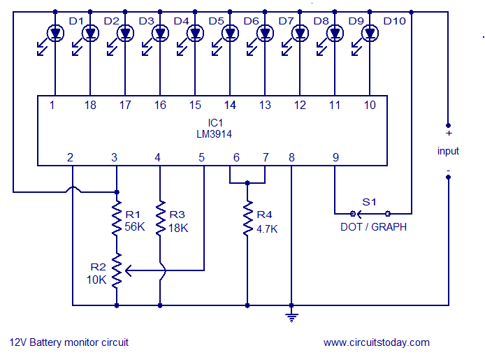
In the following circuit diagram LEDs D1 to D10 displays the level of the battery in either dot or bargraph mode. Resistor R4 connected between pins 6,7 and ground controls the brightness of the LEDs. Resistors R1 and POT R2 forms a voltage divider network and the POT R2 can be used for calibration.
The circuit shown here is designed in order to monitor between 10.5V to 15V DC. The calibration of the circuit can be done as follows. After setting up the circuit connect a 12V DC source to the input. Now adjust the 10K POT to get the LED10 glow (in dot mode) or LEDs up to 10 glow (in bar mode). Now decrease the voltage in steps and at 10.5 volts only LED1 will glow. Switch S1 can be used to select between dot mode and bar graph mode. When S1 is closed, pin9 of the IC gets connected to the positive supply and bar graph mode gets enabled. When switch S1 is open pin9 of the IC gets disconnected to the positive supply and the display goes to the dot mode.
With little modification the circuit can be used to monitor other voltage ranges. For this just remove the resistor R3 and connect the upper level voltage to the input. Now adjust the POT R2 until LED 10 glows (in dot mode). Remove the upper voltage level and connect the lower level to the input. Now connect a high value POT (say 500K) in the place of R3 and adjust it until LED1 alone glows. Now remove the POT, measure the current resistance across it and connect a resistor of the same value in the place of R3. The level monitor is ready.
( Moderation: ling1995 is a spammer. His buzzer/silence button question is left here because there are replies to it. Thanks to the ES member who identified ling1995. )