calling all cycle analyst gurus (help needed)

Diamondback

10 kW
Joined
Dec 15, 2008
Messages
540
Location
Sydney, Australia
Hi all.

hope everyone had a good Christmas...

anyway, off to the topic if this thread.

i have a cyclone 500W 24v kit on my bike.
i also have a CA-SA hooked up. i am attempting to hook up the current limiting feature on the CA.
according to the instruction manual (and an email i got from the store) with the use of a 3-5k resister and a diode,
i can use the current limiting features.

the problem im having is that i wired the resistor and diode in the correct places and orientation (for the diode),
but i now have zero throttle. there is a 0 - 5 v signal above the resistor (throttle side), but nothing below it (motor side).

with the resister removed (and diode left in place) i have throttle again.
i have not connected the diode line to the CA yet.

as the instructions say to use a 3k-5k resister, i went for the middle ground, and got a 3.9k one.
the diode (which does not appear to be a part of this problem) is a 1N4004 400V 1A diode.

can anyone offer info and advice on what's happening here ?

i really want to use the current limiting feature of the CA as the cyclone units do not seem to have a limit built in.
and i do not want to cook the controller. i have already seen peaks of 44A on what is supposed to be a 35A controller !

can anyone help ?
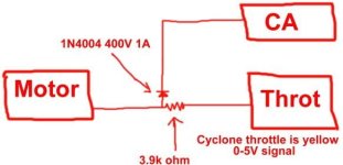
limit circuit.JPG

above is how i hooked it up.

Jason.
 
Hi Jason, I can help you with this.

You need to use a lower value resistor.

I had the same problem with my 650W Cyclone and CA-SA meter. Using the hookup as described on the CA webpage, using a 3.9K resistor resulted in almost no throttle response. I contacted Justin about this, and he suggested using a lower value resistor. He also indicated that it sounds like the Cyclone system uses a much lower impedance to the throttle input at the controller end than theCrystalyte units. You can eliminate the resistor entirely IF you have a CycelAnalyst board that says DB2 Rev7b on it. These have an internal current limit of 5mA to prevent the op-amp buffer from being damaged if it has to sink too much current from the Throttle-Override line. If not, then you could try going down to about a 1K resistor
I tried several lower ohm resistors and found with a 1K ohm resistor that it all works fine now.
 
thanks.

@Nutsandvolts.... I did indeed mean motor side.

The controller is inside the motor on the cyclone kits (on the ones up to 500W anyway).
and as for only having half the circuit, i was just testing to see if i still had a working throttle.
i was not (at that stage) expecting the CA to do anything. that's why i didn't have it connected to the CA.


@timbits .... Thanks heaps for the info.

With the 3.9k in place, the motor would not even turn. i put two of the 3.9k's in parallel (2k) and got movement.
not much though. i was going to try 1k next, but based on your suggestion, i think it will work.
i will go out today and buy some 1k resistors. that way if the 1k still does not give full throttle, i can parallel two of them
to give me 500 ohms.

My CA-SA is only about 5 weeks old, so i should be able to use 500 ohm resistance ?
the board has DB2 Rev7 printed on it (there's no b) so i don't think it wise to eliminate the resistor altogether....

how well do you find the current limiting works ?
did you alter the factory presets for the speed at witch the CA responds ?

thanks again.

Jason.
 
Hi Jason

As I recall, Justin mentioned to me he did not put the b on the board so it should be DB2 Rev7. I bought my CA in July 08 and it has the latest revision with the current limit ( it is a DB2 Rev7 ) , I think he mentioned most of the 08 units would have the current limit. Sorry for not being clear on that.
Your CA unit will have the current limit, so you should be able to eliminate the resistor entirely if you need to, although I have not tried it that way. I like the throttle response better with the 1k resistor as it seems to have given me more control over how much I have to twist the throttle to engage the motor. Originally all the range was within a small amount of twisting of the throttle grip starting from the smallest mark on the Cyclone throttle. Now with the resistor I have a small dead spot when I start to crank the throttle and at about the 2 to 3 mark the motor is engaged, and seems to have a longer amount of twist required to get to full power.I find it easier to keep the speed I want this way.

As for current limit It has helped some. I was pulling up to 55amps before ( 36v 650W Cyclone), now it is around 46-47 amps. More testing and tweaking is still in order for my case, but yes it has helped. The CA is a great help for any ebike I think
 
no problems.

i just got back from my local electronics supply place with the 1k and 500 ohm resistors.
ill try the 1k ohm one first and see how it goes.

my throttle seems to be different to yours though (as far as response goes)
i currently (stock) have nothing at all untill the second mark, then it all comes in after that point.

ill let you know how the 1k goes....

thanks again.


Jason

PS...
i tried to send a PM but it wont send for some reason. it just stays in the outbox.
 
i tried the 1k, i had full throttle, but nothing until the last few mm of travel on the throttle.
i tried the 500ohm and it got better, so i ended up putting two 500ohm resisters in parallel
for 250 ohms, and it's not perfect but i can live with it now (i think).

ill go for a ride this afternoon and try it out. if all else fails, ill just remove the resistors and try that.

Jason
 
just got back from the test ride.

bad news....

there is zero limiting going on. i have even set the speed limit at 15km/h to test it, and nothing happens.
the motor happily goes to it's top speed with no hesitation at all.
also, no amp limit even though i set it at 35A i still saw a peak of 42A.

any suggestions would be accepted at this point....


edit...Update:

i just tried the limiting features with a 1k resistor in place.
it now seems as if the limits are working, but the down side is that i now only have half the throttle travel as i did before....
i have to move the throttle about half way before i get anything from the motor.

at full twist, i am still getting full throttle though.
so it seems i have limited the resolution of the throttle, but if the limits now work, ill live with it.

Jason.
 
poor throttle resolution and a big fat dead band at the begining of the throttle is a common issue with many hall throttles. it was on my Cyclone instalations even without the addition of the CA. it is also easy to fix.

you need to add a variable resistor in series with the WHITE wire on pin#4 (GND) of the cyclone throttle. this will put the throttle a bit above ground level and allow you to set the start point. with a trimmer or variable resistor you will be able to adjust where the throttle will start to operate. normally i used 200R trimmer resistors. after setting the i find that the resistor is set to about 125~150R. just barely cracking the throttle gets the motor moving then.

but that would be on throttles without the added 1k series resistor. you may need a higher value trimmer. i would try a 1k multiturn trimmer. that way you can adjust it down to what you need. and with a multiturn pot the adjustment wouldn't be so finicky.

rick
 
thanks for the info.
ill give it a go and see...

of the trimmers on this page, which would you recommend ?

http://www.jaycar.com.au search for 1k trim pot.
the site only lists one page of them.

one other question, these have three pins, how do i connect them with the white wire ?

Jason
 
too bad Dick Smith gave up the ghost as far as real electtronics parts is concerned. i bought some of their kits just cause they were pretty good in their day. waiting for mail from down there was a pain.

anyhow JAYCAR it is. try their CAT. NO. RT4644. that would be my choice. and variable resistors have 3 pins because both ends of the resistor element have one lead each. the resistance between these 2 will always be the full value of the resistor. in this case 1k. the third pin is the variable pin. it pict of a resistance somwhere between the 2 ends. so if you measure between it and one of the ends the value will vary as you change the adjustment screw. in this case it would take 25 full turns of the adjustment screw to go from 0R to 1k.

so you need to use one end and the variable (also called "WIPER") pin. which is which changes with the design of the trimmere resistor. but usually the ones farthest apart are the ends. the one in the middle is the variable one. check which is which with your ohm meter.

rick
 
Back
Top